


12
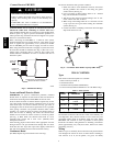
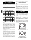
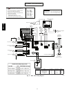
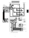
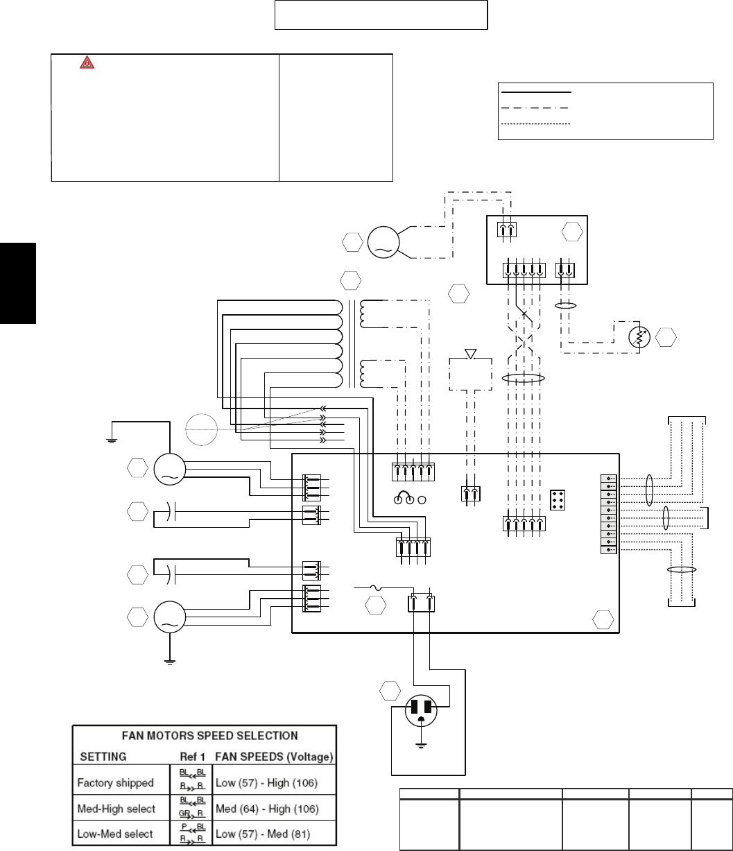
CONNECTION DIAGRAM
Line voltage factory wiring
Class 2 low voltage factory wiring
Class 2 low voltage field wiring
M1
A1
T1
R1
Field wiring
remote control
(see notes 3, 4)
120V, 60Hz
W1
F1
J5
J7
J6
J4
ELECTRONIC ASSEMBLY
1
2
3
1
2
1
2
1
2
3
12
34
12
12345
1
23
45
J8
J9
J11
J10
12
J12
J13
J14
10
9
8
7
6
5
4
3
2
1
M2
C1
C2
24V class 2
9.5V
class 2
ORG
YEL
See note 1
120V
106V
81V
neutral
GRY
WHT
Door interlock
switch
(magnetically
actuated reed
switch)
Exhaust fan motor
Exhaust fan motor
capacitor
Supply fan motor
capacitor
Supply fan motor
1
2
3
4512
12
J3
J2
J1
t
o
M3
Damper motor
Furnace blower interlock
J14-1 : NO
J14-2 : COM
J14-3 : NC
(optional; see notes 3, 5)
A2
DAMPER ELECTRONIC
ASSEMBLY
Defrost temperature
sensor
S1
ICP
RED
BLK
123
HI
JU1
MED
Ref
1
ORG
YEL
ORG
PRP
BLU
71V
64V
57V
nc
nc
nc
RED
BLU
BLU
RED
ORG
PRP
GRY
BLK
BLK
WHT
WHT
BLK
BLU
BRN
BLK
BLK
BLK
BLU
BRN
BLK
BLK
GRN
WHT
BLK
GRN
BLK
GRN
RED
YEL
GRN
(6)
BLK
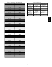
K5 K2 K3 K1 MODE M1 "Supply" M2 - "Exhaust" DAMPER
0000 OFF OFF OFF Closed
1 0 1 1 Exchange low speed LO LO Opened
1 1 1 1 Exchange high speed HI HI Opened
1 1 1 0 Circulation high speed HI OFF Closed
1 1 1 0 Defrost HI OFF Closed
COLOR CODE
BLK BLACK
BLU BLUE
BRN BROWN
GRN GREEN
GRY GRY
ORG ORANGE
RED RED
WHT WHITE
YEL YELLOW
1. : USE SPECIFIED UL LISTED/CSA
CERTIFIED LINE FUSE. Type 3AG, Littelfuse no
312003.
2. If any of the original wire, as supplied, must be
replaced, use the same equivalent wire.
3. Field wiring must comply with applicable codes,
ordinances and regulations.
4. Remote controls available.
See instruction manual. (class 2 circuit)
5. Furnace fan circuit must be class 2 circuit only.
A10001
Fig. 17 -- ERV / HRV Wiring Diagram
ERV / HRV