


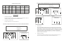

ELECTRICAL CIRCUIT DIAGRAMS FOR TSG-2G AND TSG-2F TOP ELEMENTS
ELECTRICAL CIRCUIT DIAGRAMS
FOR TSG-1G AND TSG-1F ELEMENTS
3. USE OF GRILL
Prior to using grill make sure all the protective vinyl coating has been removed from stainless
steel body. Make sure thermostat is in the off position. Plug unit into proper outlet. Turning
thermostat knob in a “clockwise” direction will turn unit on and start heating process. Pilot Light
will go out when grill surfaces have reached proper temperature. It is normal for grill surfaces to
smoke when first using unit. Smoke will disappear in 15 – 20 minutes. Place items to be
cooked on grill surface and carefully lower top onto food. Do not force. Cooking time will vary
dependent on density of items cooked.
4. GENERAL CLEANING
A brush has been included for the cleaning of the grill. Cleaning is easiest when grill is hot.
Never pour cold liquids on hot grill surface. This will cause grill plate to crack.
R1 –R2 –R3 –R4 = RESISTORS
LS = PILOT LAMP
T1 – T2 = THERMOSTATS
LS LS
• •
R1 R2
W T1 • • T2 W
• 1 2 • 3 • G • 1 • 2 • 3 •
TERMINAL BOARD
CONNECTION 220 / 240V
1
• 2• 3• G• 1• 2• 3• G•
N F
R1 LS
W •
R2
W T1 •
• 1 2 • 3 • G •
TERMINAL BOARD
CONNECTION 120V
1
• 2• 3• G•
F N
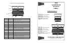
GENERAL SPECIFICATIONS
MODEL SURFACES GRIDDLE
AREA
DIMENSIONS
(W x D x H)
ELECTRICAL NEMA PLUG
TYPE
SHIP
WEIGHT
TSG-1G
ELG-1G
Grooved 14½” x 10” 15” x 12½” x 7” 120/60/1 13 Amps
1800 Watts
5-15P 53 lbs.
TSG-1F
ELG-1F
Flat 14½” x 10” 15” x 12½” x 7” 120/60/1 13 Amps
1800 Watts
6-15P 53 lbs.
TSG-2G
ELG-2G
Grooved 19¾” x 11” 20¼” x 12½” x
7”
230/60/1 7 Amps
3450 Watts
6-20P 69 lbs.
TSG-2F
ELG-2F
Flat 19¾” x 11” 20¼” x 12½” x
7”
230/60/1 7 Amps
3450 Watts
6-20P 69 lbs.
INSTALLATION
1. SETTING UP THE GRILL
The grill must be placed on a table or work area suitable for its overall dimension. Make sure
workspace is properly ventilated and free from combustible material.
2. ELECTRICAL CONNECTIONS
The grill is equipped with its own power supply cord.
ELECTRICAL CIRCUIT DIAGRAMS FOR TSG-2G AND TSG-2F BOTTOM ELEMENTS
R1 –R2 –R3 –R4 = RESISTORS
LS = PILOT LAMP
T1 – T2 = THERMOSTATS
M1 – 3 = TERMINALS
R1 R2
W LS LS W
• •
R3 R4
W T1 • • T2 W
• 1 2 • 3 • G • 1 • 2 • 3 •
TERMINAL BOARD
CONNECTION 220 / 240V
1
• 2• 3• G• 1• 2• 3• G•
N F