


UNPACKING INSTRUCTIONS
Carefully unpack the Cappuccino Dispenser Unit and inspect immediately for shipping
damage. Your Cappuccino Dispenser Unit was shipped in a carton designed to give it
maximum protection in normal handling. It was thoroughly inspected before leaving the
factory. In case of damage, contact the shipper.
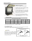
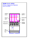
DESCRIPTION AND LOCATION OF COMPONENTS
Note: Refer to Illustrations for description and location of COMPONENTS and CONTROLS.
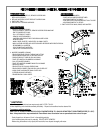
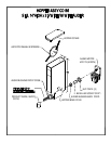
1. HOPPERS. To remove the hoppers simply swing the top compartment door open and lift out. To
reposition the canisters in the compartment, slide the canister base back until the ¼" pin at the
bottom of the base falls into the positioning hole of the compartment base.
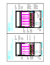
2. RINSE SWITCHES.
See diagrams inside this manual for the location of rinse switches for each individual model.
In the RINSE position they disengage the hopper motors and allow only water to be
dispensed. They are used for flushing out the Whipper Chambers and to adjust the water dispense
valves for proper flow rates.
3. HEATER SWITCHES.
See diagrams inside this manual for the location of heater switches for each individual model.
Their primary function is to shut off the heating elements during the initial priming, start up
operation of the machine, or whenever the tank is being drained for service.
4. POWER SWITCHES.
See diagrams inside this manual for the location of power switches for each individual model.
They control all power to the unit including the heater elements.
Note: The Power and Heater Switches are independent of each other. Both switches must
be OFF in order for the unit to be completely shut down.
Note: The Power Switches and Heater Switches must be ON in order for the elements to
operate.
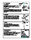
INSTALLATION INSTRUCTIONS
WATER INLET CONNECTION:
This equipment is to be installed to comply with the applicable Federal, State, or Local plumbing
codes having jurisdiction. In addition:
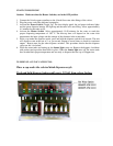
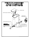
WATER CONNECTION:
GB8MP-10-LD-U: There are two (2) Water Connections. (2) ¼ inch Flare Water Inlet Fittings are
located on the left and right side in the back of unit.
GB5MV-10-LD, & GB6MP-10-LD-U: There is one (1) Water Connection, (1) ¼ inch Flare Water
Inlet Fitting located on the back of unit.
An approved back flow prevention device, such as a Double Check Valve should be installed between the unit
and the water supply.
HIGHLY RECOMMENDED:
A WATER SHUT-OFF VALVE and A WATER FILTER, preferably a combination Charcoal/Phosphate Filter, to
remove odors and inhibit lime and scale build up in the machine.
Note: In areas with extremely hard water, a water softener must be installed in order to prevent
malfunctioning of the equipment and in order not to void the warranty.