


18
Pinnacle & Stardance Direct Vent - Rear Vent Gas Heaters
20007066
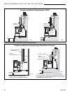
Vertical (Through the Roof)
Vent Assembly
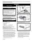
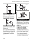
NOTE: All vertically terminated installations must,
where specified, use the 2¹⁄₄” restrictor plate, to
comply with Vertical Termination Window (Fig. 8,
Page 8), included in the hardware bag. The plate must
be installed within the firebox inner flue collar to insure
a proper air/fuel ration is maintained in an appliance
vented through the roof. (Fig. 32)
Make certain the vent system conforms to all other
requirements for vertical termination as specified on
Page 9.
This installation will require you to first determine the
roof pitch and use the appropriate vent components.
Refer to Page 10, Figure 9.
1. Locate the final position of the stove, observing all
clearances for both the vent and the stove.
2. Plumb to the center of the inner (4”) flue collar from
the ceiling above, and mark that location.
3. Cut the opening: (Page 17, Fig. 24)
9³⁄₈” x 9³⁄₈” (240 x 240mm)
4. Plumb any additional opening through the roof or
other construction that may be needed. In all cases,
the opening must provide a minimum of 1” (25mm)
clearance to the vent pipe.
5. Place the stove in its final position.
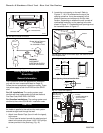
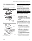
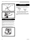
6. Install firestop(s) #7DVFS and Attic Insulation Shield
#7DVAIS as needed. (Fig. 33) If there is a room
above ceiling level, a firestop must be installed on
both the bottom and top sides of the ceiling joists. If
an attic is above ceiling level, an attic insulation
shield must be installed.
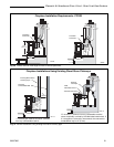
7. Install the appropriate roof support and flashing,
making certain that the upper flange of the flashing
base is below the shingles. (Fig. 34)
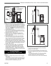
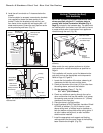
Waterproof Seal
Around Pipe
Firestop
Drain
4” Clearance
Snorkel
Termination
Cap
Wall Screws
and Anchors
ST218a
Gravel
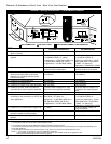
Fig. 30 Snorkel kit installation.
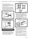
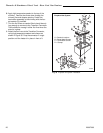
Window Well
Recessed Wall
Sheet Metal
Screws and
Bracket
Wall Screws
and Anchors
Waterproof Seal
Around Pipe
ST219
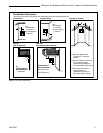
Fig. 31 Use extension brackets to mount snorkel against
recessed wall.
Firestop
Finishing
Collar
7” Pipe
Wall Plate
6. Level the soil to maintain a 4” clearance below the
snorkel.
If the foundation is recessed, use extension brackets
(not supplied) to fasten the lower portion of the
snorkel. Fasten the brackets to the wall first, and
then fasten to the snorkel with self-tapping #8 x 1/2”
sheet metal screws. Extend the vent pipes out as far
as the protruding wall face. (Fig. 31)
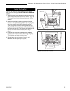
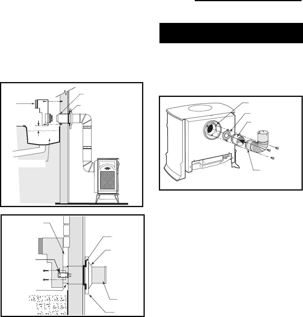
Inner Flue Collar
2¹⁄₄” Restrictor Plate
Vent Starter Pipe
Seal all
around
crimped end
ST398c
Fig. 32 Install restrictor plate and starter pipe/inner elbow
assembly.