


14
Pinnacle & Stardance Direct Vent - Rear Vent Gas Heaters
20007066
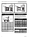
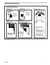
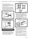
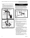
2. Locate the vent opening on the wall. Refer to
Figures 17, 18 & 19 to determine the top of the
opening centerline. It may be necessary to first
position the stove and measure to find the hole
location. Depending on whether the wall is made of
combustible materials, cut the opening to the size
shown in Figure 17. Combustible wall openings must
be framed as shown in Figure 17.
27³⁄₈"
(695mm)
to Top of
Opening
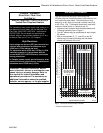
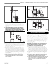
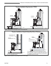
Firestop
Ventilated Wall Plate -
Open End Down
Finishing Collar
Seal
Around
Terminal
9³⁄₈” W x 10³⁄₈” H
Wall Opening
ST400
Wall Sleeve -
Seal Around
Fig. 18 SDVR with Rear Vent Kit 7TFSRSK installation.
9³⁄₈"
(240mm)
10³⁄₈"
(265mm)
7¹⁄₂" Dia.
(190mm)
VO584-100
Fig. 17 Locate vent opening.
Framing Detail
Vent Opening - Combustible Wall
Vent Opening -Noncombustible Wall
Venting System Assembly -
Direct Vent
General Information
The PDV20 and SDVR are approved for installation
only with the vent components listed on Page 13.
Follow the vent component instructions exactly. These
instructions apply to both the PDV20 and the SDVR
shell.
For U.S. installations: The venting system must
conform with local codes and/or the current National
Fuel Gas Code, ANSI Z223.1/NFPA 54
For Canadian installations: The venting system must
conform to the current CSA B149.1 installation code.
Rear Vent
Use Rear Vent Kit 7TFSRSK for an installation where
the heater is parallel to the wall and the vent system
extends straight back through that wall.
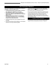
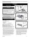
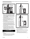
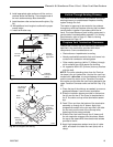
1. Attach Inner Starter Pipe, (found in with the logset),
to the stove.
• Run a bead of sealant beneath the pipe bead and
attach to the stove using three 1/4-20 x 3/8” phillips
screws provided in the parts bag. (Fig. 16)
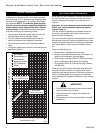
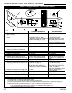
MOTOR
SNAPSTAT
ON/OFF
RHEOSTAT
WHT
WHT
BLK
BLK
BLK
GRN
BLK
Blower Wiring Diagram
Fan Assembly
No. 000-2960 / FK28
WARNING:
DISCONNECT
ELECTRICAL SUPPLY
BEFORE SERVICING
Fig. 15 Blower wiring diagram.
Sealant
Phillips
Screws
ST396a
Fig. 16 Apply sealant to the starter pipe, and fasten to stove
with Phillips screws.
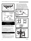
Rheostat
Retaining Nut
Rheostat Knob
FK104
Fig. 14 Attach rheostat to bracket.