


15
LDVT Series Direct Vent GaS Fireplace
10007852
FP1242
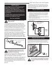
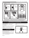
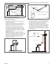
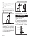
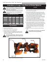
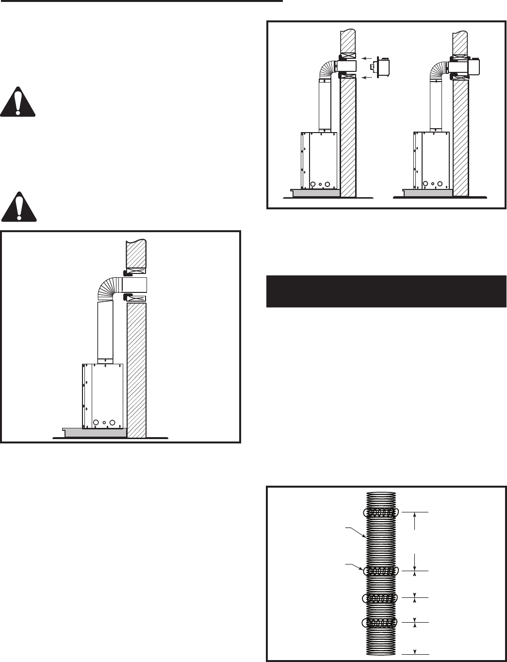
Fig. 22 Through the wall.
STEP 5
Measure the horizontal length requirement including
a 2” (51 mm) overlap, ie from the elbow to the outside
wall face plus 2” (51 mm) (or the distance required if
installing a second 90° elbow). (Fig. 21)
Always install horizontal venting on a level
plane.
STEP 6
Use appropriate length of pipe sections - telescopic or
fixed - and install the horizontal vent sections. The sec-
tions which go through the wall are packaged with the
starter kit, and can be cut to suit if necessary. (Fig. 22)
Sealing vent pipe and firestop gaps with
high temperature sealant will restrict cold
air being drawn in around fireplace.
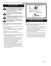
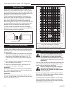
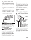
STEP 7
Guide the vent terminations 4” and 7” collars into their
respective vent pipes. Double check that the vent pipes
overlap the collars by 2” (51 mm). Secure the termina-
tion to the wall with screws provided and caulk around
the wall plate to weatherproof. (Fig. 23) As an alterna-
tive to screwing the termination directly to the wall you
may also use expanding plugs or an approved exterior
construction adhesive. You may also attach the termi-
nation with screws through the inner body into the 4”
(102 mm) vent pipe however for this method you must
extend the 4” (102 mm) pipe approximately 6” (152
mm) beyond the outer face of the wall.
FP1243
Fig. 23 Apply high temperature sealant to collars or termina-
tions.
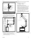
Support horizontal pipes every 3’ (914 mm) with metal
pipe straps. Make sure the horizontal vent pipe is in-
stalled on a level horizontal plane.
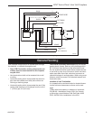
Vertical Sidewall Installation
Flex Vent Pipe
NOTE: The 40” (1016 mm) flex vent is used for 90° off
the top of the unit then out the back wall.
Follow Step 1 and 2 on Page 14.
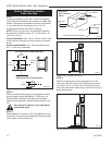
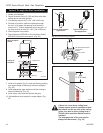
Step 3
Install the four (4) spacer springs on the 4” flex vent
pipe. When installing the spacer springs around the 4”
pipe, stretch the spring to approximately 15” (381 mm),
wrap the spring around the pipe and interlock the ends
of the spacer spring approximately 2” (51 mm). Meas-
ure 6³⁄₄” (172 mm) from the end of the pipe. Place the
next spring 5” (127 mm) from the previously installed
spring. Place the next spring 6” (152 mm) from the last
spring. Finally place the last spring 12” (305 mm) from
the last spring installed. (Fig. 24)
12"
(305mm)
6"
(152mm)
5"
(127mm)
6"
(172mm)
FP1474
spacer springs
4/04 djt
4” Flex Vent
Pipe
Spacer Spring
FP1474
Fig. 24 Install spacer springs.