


16
Pinnacle & Stardance Direct Vent - Rear Vent Gas Heaters
20007066
Side Wall Termination Assembly
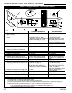
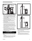
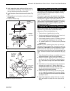
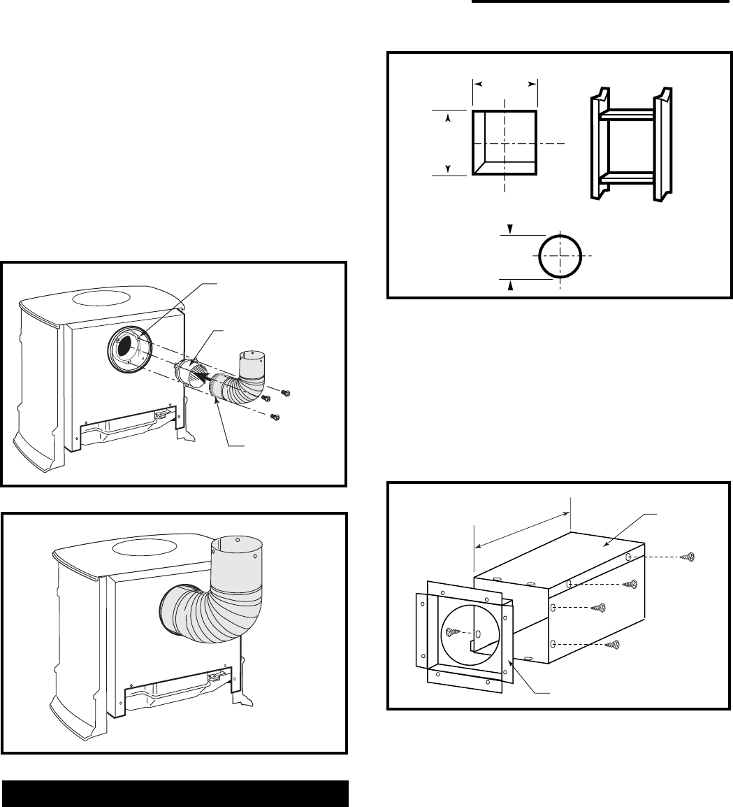
1. Locate the vent opening on the wall. Refer to
Figures 20 & 21, to determine the minimum
centerline of wall opening. It may be necessary to
first position the stove and measure to find the hole
location. Depending on whether the wall is made of
combustible materials, cut the opening to the size
shown in Figure 24. Combustible wall openings
must be framed as shown in Figure 24.
Fig. 24 Locate vent opening.
VO584-100a
9³⁄₈"
(240mm)
9³⁄₈"
(240mm)
7¹⁄₂"
(191mm)
Vent Opening - Combustible Wall
Vent Opening - Noncombustible Wall
12”
(305mm)
Max. Length
Sleeve
#8 Sheet
Metal Screws
Firestop
ZCS103
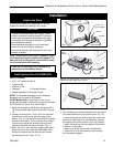
Fig. 25 Assemble the wall sleeve and firestop.
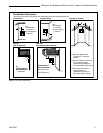
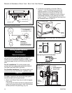
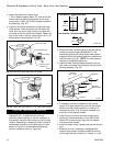
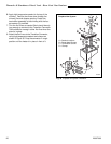
4. Attach the elbow to the starter pipe.
• Run a bead of sealant about 1/2” from end of the
starter pipe and attach the assembly to the stove
using three 1/4-20 x 3/8” Phillips screws provided in
the parts bag. (Fig. 22)
5. Install the first elbow and secure using three sheet
metal screws. Insert the elbow over the stove flue
collar. Also, be sure to align holes on the pipe with
the holes on the flue collar of the firebox. Fasten the
pipe to the holes in the flue collar with the #12 x 1/2”
sheet metal screws provided. (Fig. 23)
Inner Flue Collar
Vent Starter Pipe
Seal all around
crimped end
Inner Elbow
ST398b
Fig. 22 Install inner starter pipe and inner elbow.
ST479a
Fig. 23 Fasten outer pipe with #12 x 1/2” sheet metal screws.
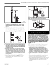
2. Measure the wall thickness and cut the wall sleeve
sections to proper length (MAXIMUM 12”). As-
semble the sleeve with the #8 sheet metal screws
supplied. Attach the firestop plate to the sleeve end
with the holes. (Fig. 25) NOTE: The wall sleeve is
required in combustible walls only.
3. Install the Wall Firestop/Sleeve assembly into the
wall cutout and fasten the firestop to the wall cutout
framing members. (Fig. 25)
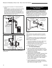
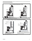
4. If necessary, measure to determine the vertical
length (X) of pipe required from the first (transition)
elbow to the wall cutout centerline, including a 2”
overlap at the joint. (Fig. 26) Use a hacksaw or tin
snips to trim the pipe as needed.
5. Install first the inner then the outer straight pipe
section(s), trimmed end down, to the point of the
elbow. Drill 3 holes through each joint and fasten
with sheet metal screws.
6. Install the elbow using 3 sheet metal screws at each
joint.
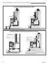
7. Measure, and cut if necessary, the appropriate
length of pipe section needed to make the connec-
tion through the wall. Include a 2” overlap; i.e. from