


14
LDVT Series Direct Vent Gas Fireplace
10007852
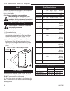
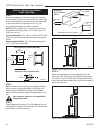
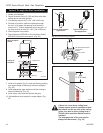
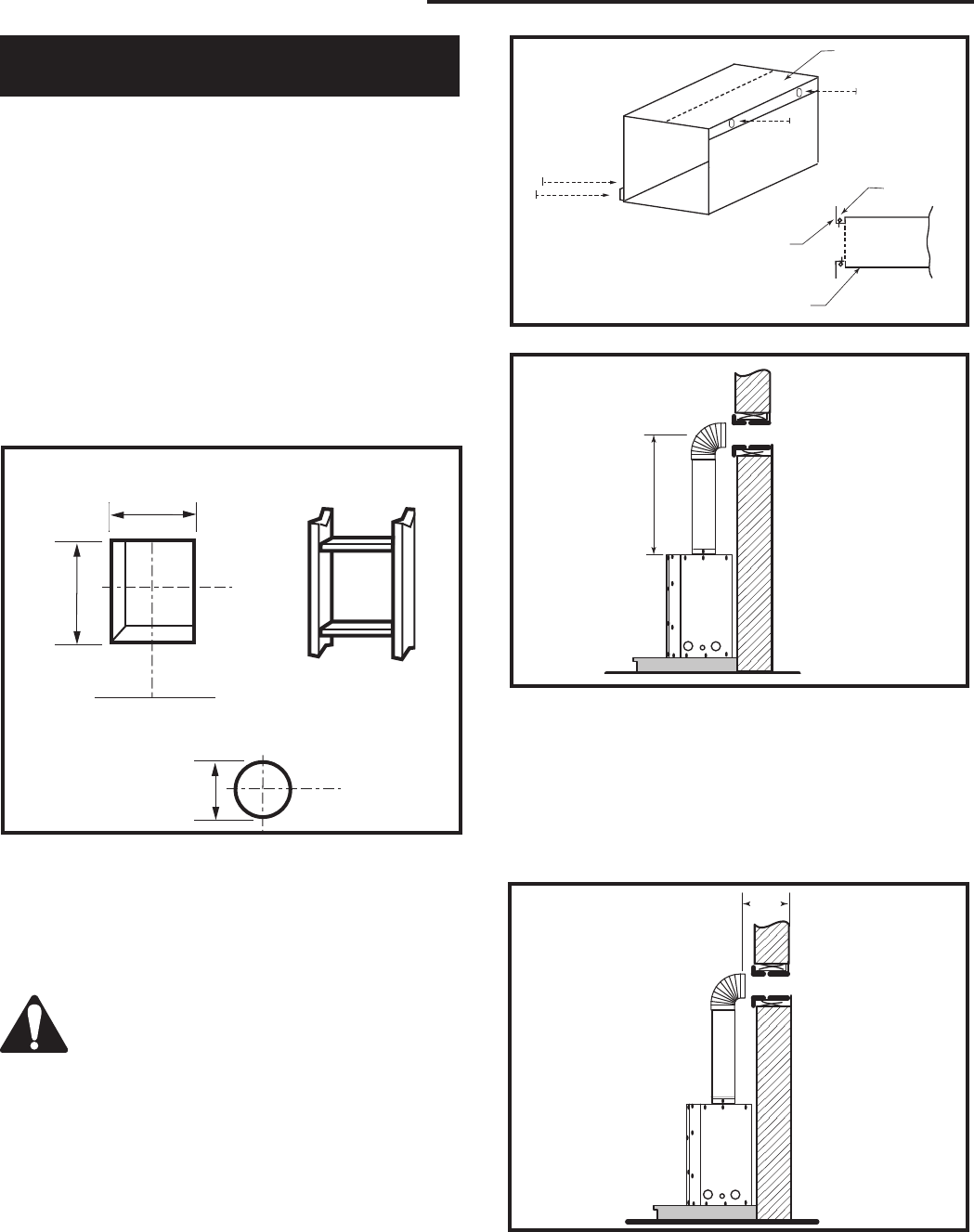
STEP 1
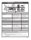
Locate vent opening on the wall. It may be necessary
to first position the fireplace and measure to obtain hole
location. Depending on whether the wall is combustible
or noncombustible, cut opening to size. (Fig. 18)
For combustible walls first frame in opening.
NOTE: When using flex vent, the opening will have to
be measured according to the 1/2” (13 mm) rise in 12”
(305 mm) vent run.
Combustible Walls:
(Fig. 18) Cut a 9³⁄₈”H x 9³⁄₈”W (240
x 240 mm) hole through the exterior wall and frame as
shown.
Noncombustible Walls:
(Fig. 18) Hole opening must
be 7¹⁄₂” (190 mm) in diameter.
Vertical Sidewall Installation
Twist Lock Pipe
VO584-100
Vent Opening
2/99 djt
Vent Opening for Combustible Wall
9³⁄₈”
(240mm)
9³⁄₈”
(240mm)
Fireplace Hearth
Framing
Detail
Opening for Noncombustible Wall
7¹⁄₂”
(190mm)
VO584-100
Fig. 18 Locate vent opening on wall.
X
FP1240
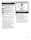
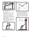
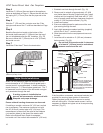
Fig. 20 Vertical height requirement.
X
FP1241
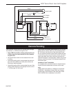
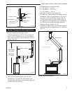
Fig. 21 Horizontal length requirement.
ZCS101
Zero Clearance Sleeve
3/11/99 djt
Max. Length
12” (305mm)
#8 Screws (2)
#8 Screws
(2)
Adjustable
Zero Clearance
Sleeve
#8 Screws
(2)
Adjustable Zero Clearance Sleeve
ZCS101
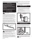
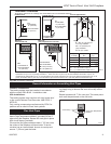
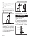
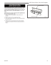
Fig. 19 Adjustable zero clearance sleeve.
Firestop
STEP 2
Measure wall thickness and cut zero clearance sleeve
parts to proper length (MAXIMUM 12”/305 mm). As
-
semble sleeve and attach to firestop with #8 sheet
metal screws (supplied). Install firestop assembly. (Fig.
19)
Zero clearance sleeve is only required for
combustible walls.
STEP 3
Place fireplace into position. (Fig. 20) Measure the ver
-
tical height (X) required from the base of the flue collars
to the center of the wall opening.
STEP 4
Attach the appropriate venting component(s) to the
inner and outer flue collars of the fireplace using three
(3) screws. (Fig. 21) Follow with the installation of the
inner and outer elbow. Again secure joints with three (3)
sheet metal screws.