


7
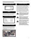
The Vermont Castings Majestic Products Company
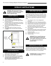
Any electrical repairs or rewiring of this unit should be carried out by a licensed electrician in accordance with national
and local codes.
If repairing or replacing any electricial component or wiring, the original wire routing, color coding
and securing locations must be followed.
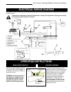
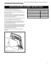
ELECTRICAL WIRING DIAGRAM
OPERATING INSTRUCTIONS
MAIN ON/OFF SWITCH
The On/Off switch supplies power to
all of the functions of the fireplace. It
is located on the top of the firebox at
the rear of the unit.
WARNING: During any service of
this appliance, the power to the
unit must be turned off. It is not
acceptable to use the “On/Off”
switch to meet this requirement.
The Heater Control acts to turn the
heater on and off as well as setting the
comfort level in the room. Turning the
knob clockwise from the off position
will place the heater into operation.
The further the knob is rotated
clockwise, the higher the set point
temperature. Turning the knob
counterclockwise will lower the set
point temperature. Turning it all the
way counterclockwise will turn the
heater function off.
HEATER CONTROL
7
BLACK
1 WHITE
1 WHITE
WHITE
5 BLACK
6
5
BLACK
WHITE
3 RED
2 BLACK
4 BROWN
BLACK
7 WHITE
(OPTIONAL)
BREAKER CIRCUIT
4
BOMAX FAN/HEATER WIRING DIAGRAM
ELEMENT
HEATER
3 RED
7 WHITE
MOTOR
FAN
10
8
6 BLACK
LIMIT
8
60 WATT
60 WATT
7
SWITCH
12
9
1
6
2
3
ELEMENT
HEATER
3 RED
5 BLACK
4 BROWN
BLACK
7 WHITE
BLACK
WHITE
WHITE
WHITE
7 WHITE
MOTOR
FAN
THERMOSTAT
MOTOR
FLAME
Temperature
Control
ON/OFF
Switch
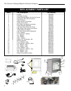
Figure 2:
Control locations at
the top rear corner of
the fireplace.
1. 120v Motor AC
2. Rocker Switch
3. Thermostat
4. Fan/Heater
5. Light Socket w/ Wiring Assy (2 Lamp)
6. Light Bulb 60 W
7. Nylon Cable Tie 6 -1/8 Black
8. Busing Snap Hole
9. Busing Strain Relief
10. Power Cord
11. CFM-Majestic Factory Wire
12. Breaker Circuit Manual Reset