


- 35 -
EB1
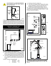
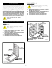
1. Slide fan assembly from the left side into fireplace
opening, line up mounting holes with screw studs on
rear of fireplace and fasten with #10-24 hex nuts.
2. Install thermal sensor on bottom of firebox using
#10-24 hex nuts.
3. (Option A) - Place electronic fan speed control box
on bottom of fireplace base, lining up mounting
holes with screw studs. Fasten fan speed control
box with #10-24 hex nuts.
(Option B) - The speed control can be installed in
an electrical box at normal wall switch height for
convenient access.
4. Remove electrical knockout on the left rear side of
the fireplace. (See hard wire or receptacle hook up
instructions).
5. Whether wiring directly to the fan junction box or into
the EB1 (electrical receptacle box, P/N ZA1200),
first ensure cable is secured using box connector.
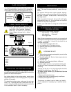
FAN KIT - FK24
Fan Specifications: 120 Volt 60 HZ .75 Amp.
This fan does not need regular maintenance, however
periodic cleaning is required. Check the area under the
control door and in front of the fan and wipe or vacuum
at least once a month during the operating season.
Should this fan require servicing, the
power supply must be disconnected.
The FK-24 comes with the electrical
cord attached.
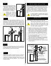
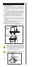
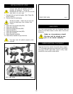
C
B
A
Black
White
Ground
A: SPEED CONTROL
B: TEMPERATURE SENSOR
C: FAN
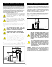
THE FIREPLACE, WHEN INSTALLED MUST BE
ELECTRICALLY CONNECTED AND GROUNDED IN
ACCORDANCE WITH LOCAL CODES OR, IN THE
ABSENCE OF LOCAL CODES, WITH THE CURRENT
CSA C22.1 CANADIAN ELECTRICAL CODE or for
U.S.A. INSTALLATIONS, FOLLOW LOCAL CODES AND
THE NATIONAL ELECTRICAL CODE, ANSI/NFPA NO.
70.
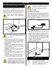
Wiring Instructions:
Hard (DIrect) Wire Hook-Up
First connect ground wire to ground stud located on the
base of either box. Black wire from supply should connect
to the variable speed switch. Alternate speed switch wire
connects to temperature sensor. Alternate lead from
sensor connects to fan. Alternate fan lead connects back
to the white supply wire. (Fig. 76).
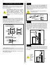
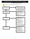
EB1 (Receptacle) Hook-Up
1. Remove 3/4" knock out. Slide the electrical box back
plate into the lance clips on bracket on bottom of
fireplace. Fasten into place with nuts provided. Fig. 77.
2. Connect the black positive wire to brass screw (polar-
ized side) of the receptacle. The white wire is connected
to the chrome screw. The ground wire is connected to
the green ground screw of the receptacle. Fit the
receptacle into the electrical box.
3. Screw the cover plate provided to the electrical box.
4. Plug in the FK24 Fan Kit.
Any electrical re-wiring of this fan must
be done by a qualified electrician.
Turn off all power before hook-up.
Fig. 75
Fig. 76
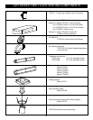
REMOTE CONTROL
MRC1 - On/Off Buttom Remote Control
MRC2 - Temperature Control Remote
MRC3 - Temperature Control with digital display
and 24 hour programmable clock.
IMT - Wall mounted thermostat control
OPTIONS
NUTS
EB1
Fig. 77