


- 13 -
Fig. 21
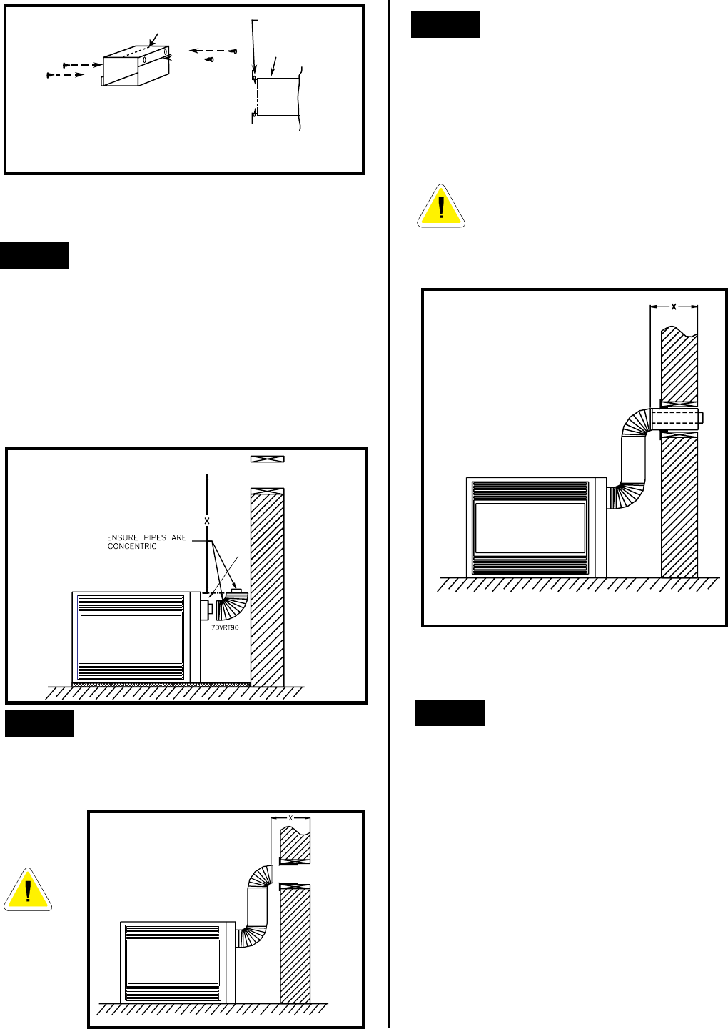
Fig. 20
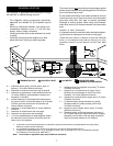
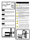
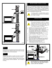
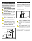
STEP 4
(Fig. 22) Measure the horizontal length requirement
including a 2" (50mm)overlap, i.e. from the elbow to the
outside wall finish plus 2" (or the distance required if
installing a second 90º elbow).
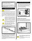
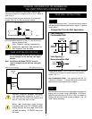
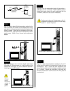
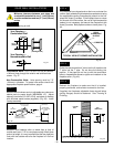
STEP 3
(Fig. 21) Apply a bead of high temperature sealant to the
inner and outer flue collars of the fireplace and using
appropriate venting component(s) attach to fireplace with
three (3) screws. Follow with the installation of the inner
and outer elbow. Again secure joints with three (3) sheet
metal screws. Wipe off any excess high temperature
sealant.
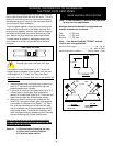
Always
install
horizontal
venting on
a level
plane.
#8
SCREWS(2)
ADJUSTABLE ZERO
CLEARANCE SLEEVE
ADJUSTABLE
ZERO CLEARANCE
SLEEVE
#8
SCREWS(2)
#8
SCREWS(2)
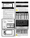
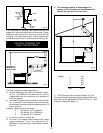
Maximum Length
12" (294mm)
FIRESTOP
Fig. 22
BEAD OF
SILICONE
Sealing vent pipe and firestop gaps with hi-
temperature sealant will restrict cold air being
drawn in around fireplace.
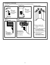
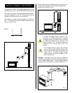
STEP 5
(Fig. 23) Use the appropriate length of pipe section –
telescopic or fixed – and install. The 20" (508mm) section
of pipe which goes through the wall is packaged with the
7DVSK kit, and can be cut to suit if necessary.
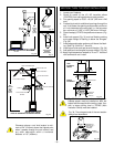
STEP 6
(Fig. 24) Apply high temperature sealant to 4" and 7"
collars one inch away from crimped end. Guide the vent
termination 4" and 7" collars into their respective vent
pipes. Double check that the vent pipes overlap the collars
by 2" (50mm). Secure the termination to the wall with
screws provided and caulk around the wall plate to
weatherproof.
Fig. 23