


9
10004894
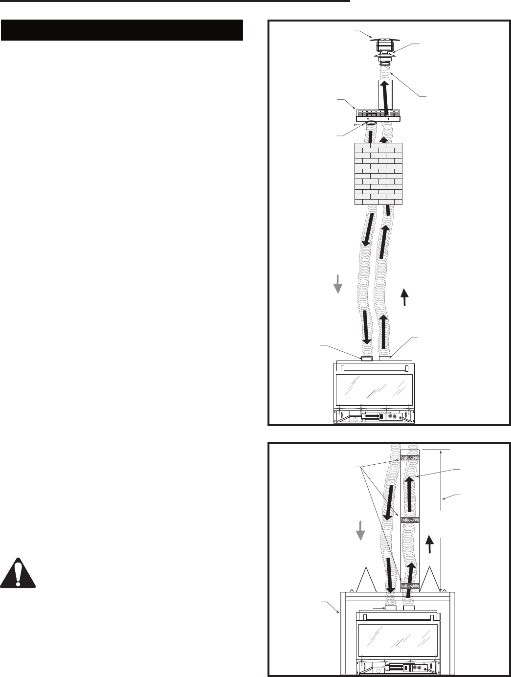
LHEDV Series Direct Vent Insert
Liner Installation
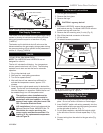
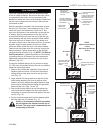
The collar extending down from the termination base
is the air intake connector. Be sure the flex vent, which
is connected to this collar, is also connected to the
labelled air intake flue collar on the fireplace. Make sure
the flex vent is attached on the correct collar and cap
for exhaust as well.
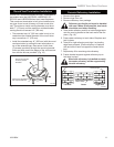
Slide the insulation provided in the termination kit over
the two (2) 3" flex liners, (to be attached to the 3" flue
collar and cap of the termination). Feed one 3" flex
vent from the bottom of the termination up through the
4" sleeve. Apply hi-temp sealant on the rain cap col-
lar and slide the flex vent over the end of the rain cap
collar fastening with the clamp provided. Slide the flex
liner back down the 4" sleeve until 4" cap slides over
the sleeve. Attach cap to the sleeve with four (4) screws
supplied. Apply hi-temp sealant over the air intake
collar and attach intake flex vent in the same method.
Feed the two flex liners down the chimney through the
damper opening. Tighten termination to the chimney
using the screws provided. (Fig. 10) NOTE: For Round
Vent Terminations - tighten termination to the chimney
by pushing the four (4) straps of the vent termination
against the chimney and secure with four (4) screws
provided. (Fig. 12)
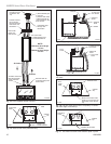
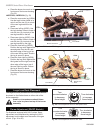
In case the fireplace opening is only minimum height
21" (533 mm) and access from the front is not possible,
follow the instructions below.
1. Remove flue collar plate assembly. Unbolt the top
fastener plate and move it to the back first before
sliding the flue collar plate out from the top of the
unit. (Fig. 13)
2. Apply a bead of hi-temp sealant on the end of the
collar before attaching the liner to the flue collar.
Fasten it with two clamps then adjust fastener plate
all the way to the back before sliding flue gas plate
back onto the unit. (Figs. 14 and 15)
3. After the flue collar plate is set on the cabinet top,
make sure the front edge of the flue collar plate is
completely in contact with the back edge of the cabi-
net top. (Fig. 16)
4. Put the machine screw back into the fastener plate.
Bolt the plate until it is locked. (Fig. 17)
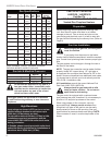
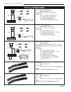
Under no circumstances should insulation
be put between the damper and the top of
the unit. This may cause condensation and
overheating of the unit.
FP1280
RHEDV
vent termination
1/03
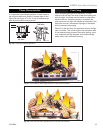
Flue gas exits
through the
vent termination
rain cap
1) Attach flexible pipe
to rain cap
2) Secure with clamp
3) Attach raincap to
vent termiantion us-
ing three screws
Pull flexible pipe
through vent
termination
Outside combustion
air enters through the
lower level of the vent
termination
Secure with
clamp and
three screws
NOTE:
Minimum Vent Height
- 12 feet
Maximum Vent Height
- 35 feet
Air Intake
Exhaust
Air intake collar with
label secured with
clamp and three
screws
Exhaust collar secured
with clamp and three
screws
FP1280
Fig. 10 Liner installation.
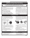
FP1280a
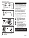
LHEDV
vent termination
w/zero clearance kit
4/03
6ft.
(183cm)
Spring located in
between the liner
and chimney kit
HEDVCAK
Installation
Secure this
kit with three
(3) screws
provided
HEZC Zero
Clearance Kit
Air Intake
Exhaust
FP1280a
Fig. 11 Liner installation with zero clearance kit.