


MSMVPU/LSMVPU Installation Instructions
10
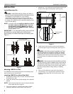
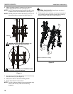
2. Adjust Velcro® pull strap (if necessary) so it does not
extend beyond bottom of screen. (See Figure 11)
NOTE: Do NOT allow both interface brackets (U and V) to be
located on same side of wall bracket. (See Figure 11)
NOTE: NEVER place both interface brackets (U and V) to one
side of the wall mount center line! (See Figure 11)
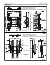
Figure 11
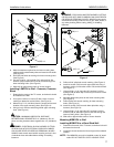
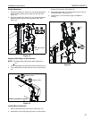
3. Hang top hook of interface brackets (U and V) onto the top
bar of the mount (R). (See Figure 12)
4. Slide screen and bars to desired viewing position.
5. Route cables between wall and bars.
NOTE: The pull-out feature allows the screen to be pulled away
from the wall for easy cable access following
installation.
CAUTION: PINCH POINTS! Keep fingers, hands and
cables out of pinch point areas.
6. Pull downward on the pullstraps and swing inward toward
wall, latching interface brackets to lower bar and locking
bottom of screen to the mount. (See Figure 12)
Figure 12
Both interface brackets must NEVER be located
to one side of the wall brackets!
Pullstrap
NEVER place both interface brackets to one
side of the wall mount center line (CL)!
Center Line (CL)
3
6
Top
Hook
(Screen not shown for clarity)
Pullstraps