


MSMVPU/LSMVPU Installation Instructions
6
INSTALLATION
Locate Mounting Site
WARNING: IMPROPER INSTALLATION CAN LEAD TO
MOUNT FALLING CAUSING SEVERE PERSONAL INJURY
OR DAMAGE TO EQUIPMENT! It is the installers
responsibility to make certain the structure to which the
mount is being attached is capable of supporting five times
the weight of the LSMVPU and all attached equipment not to
exceed 150 lbs (68 kg).
NOTE: Proceed to either the Installing LSMVPU to a Wood
Stud Wall, Installing LSMVPU to Wall - Concrete,
Concrete Block; Installing MSMVPU to a Wood
Stud Wall or Installing MSMVPU to Wall - Concrete,
Concrete Block section.
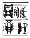
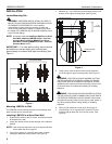
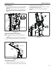
IMPORTANT ! : For video wall mounting, mounts should
be installed one screen height apart vertically and
approximately one screen width apart horizontally. (See
Figure 1)
Figure 1
Mounting LSMVPU to Wall
The LSMVPU has been designed to be mounted directly onto
either a wood stud or concrete wall.
Installing LSMVPU to a Wood Stud Wall
1. Determine the center of the TV screen, and where it should
be located on the wall.
2. Locate the closest stud to the left and right of the selected
location.
NOTE: If the screen area lies over a stud, use that stud and the
stud to either the left or right of it.
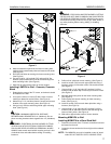
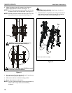
3. Line up the notches on mount (R) with center of screen
marking to determine vertical center. (See Figure 2)
4. Measure up 7-1/2" (190.5mm) from the center point to mark
location of the upper mounting slots. (See Figure 2)
Figure 2
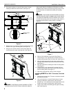
5. Using a level, mark the wall on each stud to attach the
mount through the upper mounting slots. (See Figure 3)
WARNING: ELECTRICAL SHOCK HAZARD! CUTTING
OR DRILLING INTO ELECTRICAL CORDS OR CABLES
CAN CAUSE DEATH OR SERIOUS PERSONAL INJURY!
ALWAYS make certain area behind mounting surface is free
of electrical wires and cables before drilling or installing
fasteners.
WARNING: EXPLOSION AND FIRE HAZARD! CUTTING
OR DRILLING INTO GAS PLUMBING CAN CAUSE DEATH
OR SERIOUS PERSONAL INJURY! ALWAYS make certain
area behind mounting surface is free of gas, water, waste, or
any other plumbing before cutting, drilling, or installing
fasteners.
6. Drill one 7/32" pilot hole in each stud. (See Figure 3)
7. Use two 5/16 x 2-1/2" lag bolts (QC) and two 5/16" flat
washers (QB) to attach top of mount (R) to wall. (See
Figure 3)
one screen width
one screen height
Center of screen
7-1/2"
Vertical center
of mount
(190.5mm)