


(NOT
T
O SCALE)
SECT
.
III P
AGE
2
0707
Litho in U.S.A.
Each compartment has capacity for:
•
Three, 12˝ x 20˝ x 2
1
⁄2˝ or six, 12˝ x 20˝ x 1˝ deep
Cafeteria Pans.
WATER QUALITY REQUIREMENT
The recommended minimum water quality standards
whether untreated or pre-treated, based upon 10 hours of
use per day, and a Daily Blowdown, are as follows:
TOTAL DISSOLVED SOLIDS less than 60 parts per million
T
OTAL ALKALINITY less than 20 parts per million
SILICA less than 13 parts per million
pH FACTOR greater than 7.5
C
HLORINE less than 30 parts per million
Consult a local water treatment specialist for an on site
water analysis for recommendations concerning steam
generator feed water treatment (if required), in order to
r
emove or reduce harmful concentrations of minerals. The
use of highly mineralized water will mean that more
frequent servicing of the steam generator will be necessary.
The fact that a water supply is potable is not proof that it
will be suitable for the generator
.
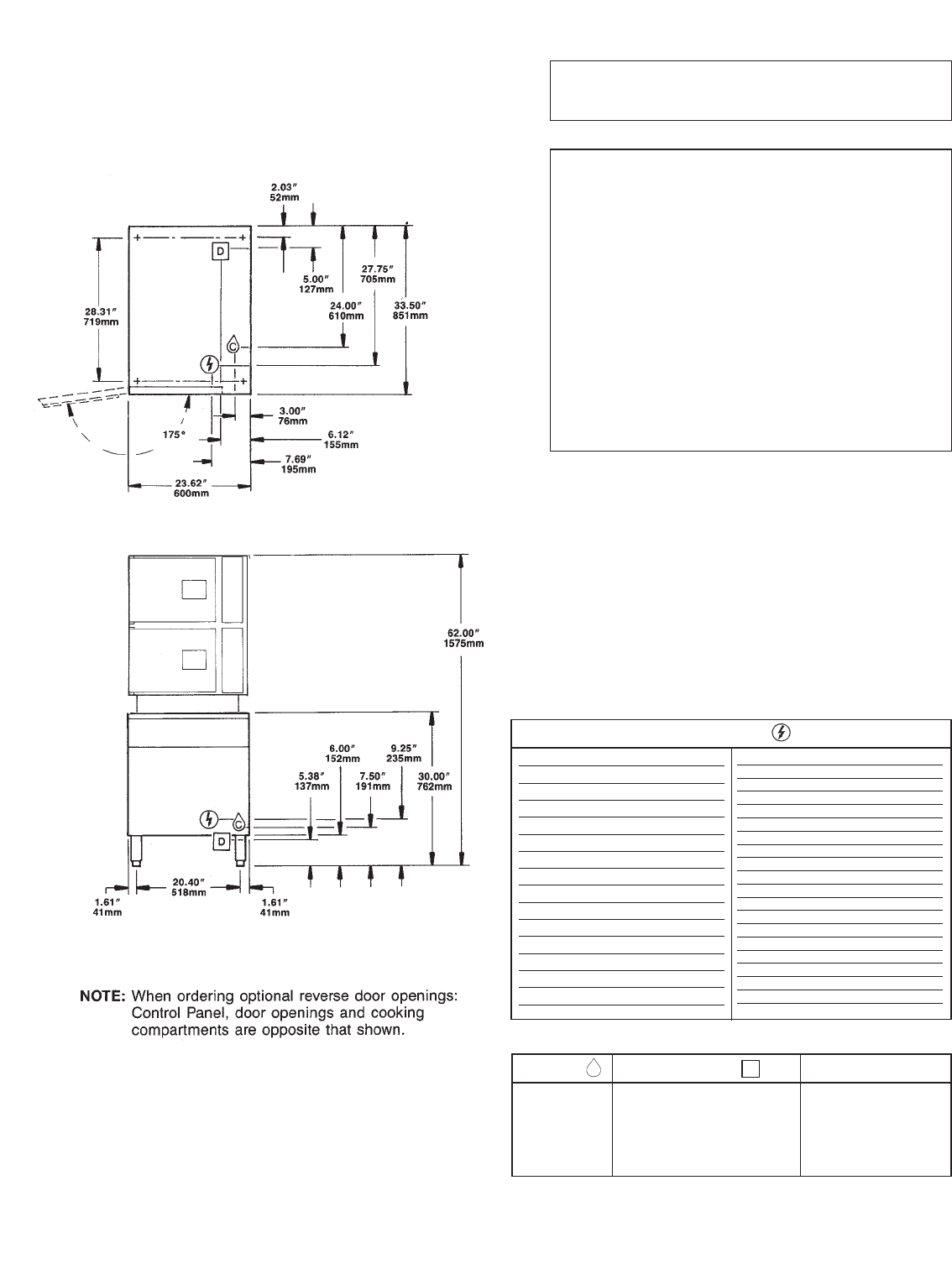
KW Volts Watts
Ph
Amps Wire
24 208 21,500 1 103.4 2
220 24,000 1 109.1 2
240 24,000 1 100.0 2
440 20,200 1 45.9 2
480 24,000 1 50.0 2
208 21,500 3 59.7 3
220 24,000 3 63.1 3
240 24,000 3 57.8 3
440 20,200 3 26.5 3
480 24,000 3 28.9 3
600 24,000 3 23.1 3
360 21,500 3 34.5 4
380 24,000 3 36.5 4
415 24,000 3 33.4 4
KW Volts Watts
Ph
Amps Wire
36 208 32,200
3 89.5 3
220 36,000 3 94.6 3
240 36,000 3 86.7 3
440 30,200 3 39.7 3
480 36,000 3 43.4 3
600 36,000 3 34.7 3
360 32,200 3 51.7 4
380 36,000 3 54.8 4
415 36,000 3 50.1 4
48 208 42,900 3 119.2 3
220 48,000 3 126.1 3
240
48,000
3
1
15.6
3
440 40,300 3 52.9 3
480 48,000 3 57.8 3
600 48,000 3 46.2 3
360
42,900 3 68.9 4
380
48,000
3
73.0
4
415 48,000 3 66.9 4
ELECTRIC
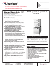
WATER DRAINAGE CLEARANCE
C
D
The Floor Drain m
ust be located
outside the confines of the
equipment base.
1 1/2˝ I.P.S. common drain.
Do not connect other units to this drain.
Do not use PVC pipe for drain.
1/4˝ NPT
Cold W
ater Inlet
35 psi minimum
60 psi maximum
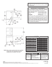
Right - 3”, Left - 3”, Rear - 3”
(12” on control side if adjoin-
ing wall or equipment is over
30” high for service acess)
Contact factor
y f
or
variances to clearances.
NO
TES
:
Cleveland Range reserves right of design improvement or modification, as warranted.
Many regional, state and local codes exist and it is the responsibility of the owner and installer to comply with the codes.
Cleveland Range equipment is built to comply with applicable standards for manufacturers. Included among those approval agencies are ASME/N. Bd, UL, NSF and CSA.