


GAS ELECTRIC COLD WATER CLEARANCE DRAINAGE
1
1
⁄
4
˝ IPS line size,
3
⁄
4
˝ connection 120V-1Phase, 60 Hz. 35 psi minimum RIGHT = 12.00˝
NATURAL PROPANE BTU 2 Blowers & Controls 60 psi maximum LEFT = 3.00˝
Piping
3
⁄
4
˝ N.P.T. Piping
3
⁄
4
˝ N.P.T. 50,000 each 150 watts each C2
3
⁄
8
˝ dia. NPT for Generator R
E
AR = 3.00˝
Supply pressure Supply pressure Generator, C1
3
⁄
8
˝ dia. NPT for Condenser Allow 6˝ space min.
4.50˝ W.C. Min. 11.00˝ W.C. Min. 100,000 total
** Do not connect to GFI
from rear and sides
14.00˝ W.C. Max. 14.00˝ W.C. Max.
outlet. See note below.
When located near
combustible walls
Manufacturer must be notified if unit will
be used above 2,000 feet
20.63"
(524mm)
33.13"
(842mm)
4.87"
(124mm)
3.00" TYP
(76mm)
7.75"
(197mm)
10.44"
(265mm)
5.00"
(127mm)
4.00"
(102mm)
12.00"
(305mm)
24.00"
(508mm)
12.76"
(324mm)
15.06"
(383mm)
17.43"
(
443mm)
37.13"
(943mm)
13.25"
(337mm)
10.00"
(254mm)
2
0.88"
(530mm)
4.75"
(121mm)
13.88"
(353mm)
20.36"
(517mm)
17.25" TYP
(438mm)
21.50"
(546mm)
59.21"
(1504mm)
30.25"
(768)
5.00"
(127mm)
7.34"
(186mm)
20.50"
(521mm)
2.06"
(52mm)
6.60"
(168mm)
33.13"
(842)
6.13"
(156mm)
24.00"
(610mm)
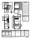
OPERATING
CLEARANCE
S
ECONDARY
CLEARANCE
C2
D
C
1
(NOT TO SCALE)
SECT. IV PAGE 12
1007
Litho in U.S.A.
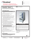
Each Compartment has
Capacity for:
• Three 2
1
⁄2˝ x 12˝ x 20˝
Steam Table Pans
• Six 1˝ x 12˝ x 20˝
Steam Table Pans
• Two 4˝ x 12˝ x 20˝
Steam Table Pans
C
NOTES:
**DO NOT CONNECT TO GFI OUTLET. CLEVELAND RANGE RECOMMENDS GAS FIRED 120 VOLT STEAMERS BE HARD WIRED DIRECTLY TO ELECTRICAL SYSTEM.
Cleveland Range reserves right of design improvement or modification, as warranted.
Many regional, state and local codes exist and it is the responsibility of the owner and installer to comply with the codes.
Cleveland Range equipment is built to comply with applicable standards for manufacturers. Included among those approval agencies are UL/NSF#4 and CSA (AGA, CGA).
D
WATER QUALITY
REQUIREMENTS
The quality of water varies
greatly from region to
region. Steam equipment
generators must be
drained daily and chemi-
cally descaled periodically
t
o ensure proper operation.
To minimize service prob-
lems caused by the accu-
mulation of minerals and
chemicals in water review
the following quality guide-
lines with a local water
treatment specialist. Inlet
water that is beyond these
specified guidelines should
be treated to achieve these
acceptable limits. Total
Dissolved Solids less than
60 ppm, Alkalinity less than
20 ppm, Silica less than 13
ppm, pH factor greater
than 7.5, Chlorine less
than 30 ppm.
Right - 3”, Left - 3”,
Rear - 3”
(12” on control side if
adjoining wall or
equipment is over 30”
high for service access)
Contact factory
for variances to
clearances.
1
1
⁄
2
˝ dia.
Do not connect other units to this
drain
Drain must not be located
beneath the steamer itself
Preferred floor drain location
should be a minimum distance
(from the unit) of at least 12” from
the left side, 12" from the right
side, 6” from the front and 6" from
the rear
Do not use PVC pipe