


GENERAL
Installation of the unit must be accomplished by qualified
installation personnel working to all applicable local and
national codes. Improper installation of product could
cause injury or damage.
This unit is built to comply with applicable standards for
manufacturers. Included among those approval
agencies are: UL, NSF, ASME/Ntl.Bd., CSA, ETL, CE,
and others. Many local codes exist, and it is the
responsibility of the owner/installer to comply with these
codes.
INSPECTION
Before uncrating, visually inspect the unit for evidence
of damage during shipping. If damage is noticed, do
not unpack the unit, follow shipping damage
instructions.
SHIPPING DAMAGE
INSTRUCTIONS
If shipping damage to the unit is discovered or
suspected, observe the following guidelines in
preparing a shipping damage claim.
1. Write down a description of the damage or the
reason for suspecting damage as soon as it is
discovered. This will help in filling out the claim
forms later. If possible, take a polaroid picture.
2. As soon as damage is discovered or suspected,
notify the carrier that delivered the shipment.
3. Arrange for the carrier's representative to examine
the damage.
4. Fill out all carrier claims forms and have the
examining carrier sign and date each form.
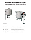
INSTALLATION
The first installation step is to refer to the Specification
Sheet for detailed clearance requirements, suggested
drain locations and bolting requirements. Next, carefully
cut open and remove the shipping carton. Remove all
supports and fasteners holding unit to the skid.
KDL SERIES
Position the kettle in its permanent location, and level
the kettle by turning the adjustable flanged feet. Once
positioned and levelled, permanently secure the kettle's
flanged feet to the floor using lag bolts and floor
anchors (to be supplied by the installer).
KDP SERIES
1. Position the kettle in its permanent location, and
mark the floor around the circumference of the
base collar or the base plate. Locate the centre of
this circle and mark the floor at this centre point.
This is the point at which the kettle's base plate will
be secured to the floor.
2. Lay kettle on its side (on a cushioned surface to
prevent scratching), and slide the base collar up
the pedestal, exposing the plate for removal.
3. Remove the four cap screws securing the base
plate and slide it off the kettle.
4. Prepare the floor location, for mounting the kettle,
by installing a 3/4" (19mm) stud, cast into the floor,
at the base plate's centre point. Note: a 3/4"
(19mm) lag bolt and floor anchor may be
substituted for a cast-in stud. The anchor is
installed in the floor, and the lag bolt is threaded
down through the base plate, into the anchor, after
completion of step 6.
5. Thread the four 3/8" (10mm) levelling bolts into
plate from the top, and insert the plate over stud.
6. Adjust bolts until the plate is level.
7. Install a nut on the 3/4" (19mm) bolt (or insert a lag
bolt if the alternate fastener method is used) and
secure base plate to the floor.
8. Check for level "set" of the kettle by placing the
kettle on the base plate with the screw holes
aligned and applying a carpenter's level at the
kettle rim. If the kettle is level, it may be fastened in
place with the four cap screws. If the kettle is not
level, the kettle must be removed from the base,
the plate loosened, and the levelling bolts re-
adjusted until a level installation is attained.
9. Slide the base collar down to the floor, and draw a
line around the circumference of the pedestal at
the top of the collar, using the top of the collar as a
guide. Slide the collar back up the pedestal.
10.
Apply a bead of silicone sealer to the circumference
of the pedestal, at the line, and also to the bottom
rim of the collar. Slide the collar down the pedestal
and press it tightly to the floor. The silicone sealer
will create a seal where the collar meets the
pedestal, and where the collar meets the floor.
SERVICE CONNECTIONS
Install service connections as required. Locations and
other data are shown on the Specification Sheet.
INSTALLATION