Phone: 317-337-9813 www.continentalchillers.com
Fax: 317-337-9816
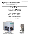
Continental Single Phase Chillers
UniPac™
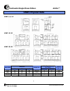
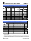
Standard Unit Specifications of UniPac™ Single Phase Chillers
General Description
Continental’s Single Phase Air and Water Cooled Chillers
are packaged systems complete with scroll compressor(s), air
cooled or water cooled condenser(s), individual
cooler/evaporator(s), independent refrigerant circuit(s) and a control
center all mounted on a heavy duty structural steel frame.
Scroll Compressor(s)
Compressors are well proven state-of-the-art scrolls with fewer
moving parts, less rotating mass, and less internal friction than
traditional reciprocating compressors.
Motor is suction gas-cooled, hermetically sealed, two pole,
squirrel cage induction type and is directly driven at 3600 rpm.
All compressor(s) are mounted on resilient pads to minimize
vibration.
Air Cooled Condenser for Air Cooled Models
Condenser Coil-industrial quality, seamless copper tube
Fins-all aluminum, die formed with full self–spacing collars that
completely cover the copper tube; fins are mechanically bonded to
the copper tubes
Propeller Fans-large surface, low speed, low sound level propeller
fans for vertical airflow; fans are statically and dynamically balanced
and operate at low tip speeds for low vibration and sound levels
Fan Guards- PVC coated for long life
Fan Venturi- high collar fully spun venturi design for high efficiency
and low outlet noise
Fan Motors-special “enclosed air over” motor design with built-in
overload protection; single phase motors operate at a low speed of
1075 rpm
Water Cooled Condenser for Water Cooled Models
Each water cooled condenser is of shell/coil design. The
condenser water flows through special heat transfer copper tube.
Refrigerant flows through the steel shell and a built in receiver.
Cooler/Evaporator for All Models
Each cooler/evaporator is of shell/coil design. The water to be
chilled flows through special heat transfer copper tube. Refrigerant
flows through the steel shell/receiver.
Refrigerant Piping
Each Refrigerant circuit includes:
• Liquid line with charging connection
• Filter drier
• Liquid solenoid valve with 115 V coil (220 V or 24 V, optional)
• Sight glass/ moisture indicator
• Suction line fully insulated, designed for proper oil return at
minimum friction loss
• Discharge line formed of clean ACR type tubing and pre-formed
radius fitting
Control Center
All power, starting, safety and operating controls are mounted in
a built in fully enclosed, weather proof control panel for air cooled
models and NEMA-1 enclosures for indoor water cooled or
condenserless models.
Power controls include:
• Single point electrical terminal block for 230/1/60 power input
• Compressor-motor contactor(s)
• Compressor run capacitor(s)
• Fan motor contactor(s) (air cooled units only)
• Control circuit fuse
• Control circuit terminal block
Safety/Operating controls include:
• Two position switch indicating off/system on – per circuit
• High Pressure control with manual reset –per circuit
• Low pressure control with auto reset – per circuit
• Adjustable chilled water temperature controller
• Adjustable freezestat
• Adjustable compressor anti-recycle timer(s)
• Relay(s)
• Built-in compressor-motor overload
Testing, Evacuation and Refrigerant Charging
Each completed system is pressure tested with nitrogen,
evacuated with a high capacity vacuum pump, vapor charged with
R-22 and fully tested for all operating and safety controls. Field
charge of R-22 required.
Split chiller systems are “dry run” tested for operating and
safety controls.
Assembly
All above components are assembled on a heavy-duty
structural steel frame, formed of channels and angles as a rugged
pre-engineered package. Each steel frame has mounting holes and
“lifting eyes” on four sides for “spreader bar” lifting and rigging.
The cabinet of air cooled units is made of heavy gauge
galvanized steel.
3


