


6
UVSTR / UVCVR Series Vent-Free Fireboxes
7412960
Installation
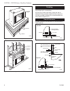
Installing Outside Air Kit
An outside air kit may be installed in all UVSTR/CVR
Series fireboxes. If desired, or if local codes man-
date the use of an air kit, then an AKU2 is required to
complete the installation (from air kit to out-of-doors).
If the outside air kit is to be used, the AKU2 MUST be
installed BEFORE the fireplace is enclosed. Refer to
the AKU2 instructions for field installation.
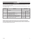
FP680
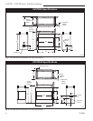
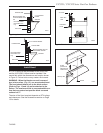
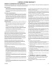
Fig. 5 Adjustable drywall strip (nailing flange).
FP680
4/20/98
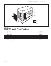
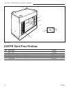
UVSTR/UVCVR36
UVSTR36
UVCVR36
Nail Top
Standoffs
Nail Eight
Side-Nailing
Flanges
Nail Top
Standoffs
Nail Four
Side-Nailing
Flanges
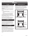
Planning
In planning the installation for the firebox it is neces-
sary to determine where the unit is to be installed and
whether optional accessories are desired. Gas supply
piping should also be planned.
These models may NOT be installed in a bedroom
or bathroom.
Glass doors are NOT available for these fireboxes.
The firebox can be mounted on any of the following
surfaces:
• A flat hard combustible surface.
• A raised platform of combustible or noncombustible
material.
• A concrete block or other solid object placed be-
neath each of the four corners of the appliance.
If the firebox is installed directly on carpeting, tile or
other combustible material other than wood flooring, it
should be installed on a metal or wood panel extending
the full width and depth of the unit.
At this point, you should have decided what compo-
nents to include in your installation, and where the
firebox is to be located. If this has not been done, stop
and consult your dealer for planning assistance.
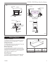
Framing
Firebox framing can be built before or after the firebox
is set in place. Framing should be positioned to ac-
commodate wall covering and firebox facing material.
The firebox framing should be constructed of 2 x 4 or
heavier lumber. The framing headers may rest on the
top of the firebox standoffs Refer to Figs. 1 and 2 for
firebox framing dimensions.
Anchor Firebox in Position
To prevent shifting of the firebox and to maintain sealing
(described later), anchor the firebox. Two methods are
possible for these fireboxes.
One method is to use the eight fastening tabs (four
with cove model) provided with the firebox. (Fig. 5) The
firebox may be secured to the vertical framing members
with these tabs and nails or other suitable fasteners.
The second method uses the standoffs at the front of
the firebox. A nail may be installed through the standoffs
and into the header to stabilize the top of the firebox.
(Fig. 5)