


Read these instructions and Operator's Manual in its en-
tirety before you attempt to assemble or operate your new
high pressure washer. Your high pressure washer has, for
the most part, been assembled at the factory, except those
parts left unassembted. Before you can operate your' new
high pressure washer, you must assemble the wheel kit and
properly connect the high pressure hose.
IF YOU HAVE ANY PROBLEMS WITH THE ASSEM-
BLY OF YOUR PRESSURE WASHER, PLEASE
CALL THE PRESSURE WASHER CUSTOMER
HELPLINE AT 1-800-222-3136.
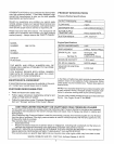
TOOLS REQUIRED FOR ASSEMBLY
• Mallet
• Socket wrench with 1/2-inch or 13ram Sockets
• Crescent Wrenches or Combination Wrenches
• 8ram nut driver
TO REMOVE
CARTON
Q
PRESSURE WASHER FROM
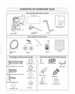
Remove guide handle (wrapped in plastic)o
Remove accessories box from carton_
Remove gun/wand assembly from cardboard holder.
Remove all other packing material from box before
removing your high pressure washer.
HOWTO SET UP YOUR PRESSURE WASHER
TO INSTALL THE WHEEL KIT
Installing wheel kit, requires the tools listed above, the
guide handle and items included in the parts carton. You
can also refer to the Parts Illustration on Page 15.
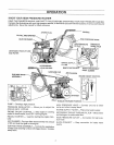
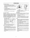
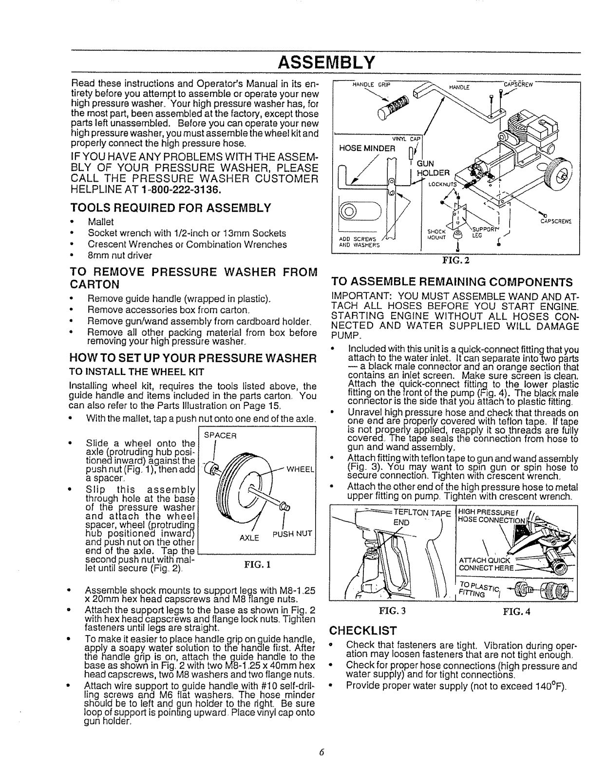
• With the mallet, tap a push nut onto one end of the axle.
Slide a wheel onto the
axle (protruding hub posi-
tionedinward) against the
push nut (Fig. 1), then add
a spacer',
Slip this assembly
through hote at the base
of the pressure washer
and attach the wheel
_pacer, wheel (protruding
ub positioned inwara)
and push nut on the other
end of the axle. Tap the
second push nut with mal-
let until secure (Fig. 2)
SPACER
AXLE PUSH NUT
FIG. 1
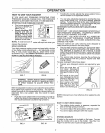
• Assemble shock mounts to support legs with M8-1 25
x 20mm hex head capscrews and M8flange nuts.
• Attach the support legs to the base as shown in Fig, 2
with hex head capscrews and flange lock nuts. Tighten
fasteners until legs are straight.
• To make it easier' to place handle grip. on guide handle,
appJy a soapy water solution to the handle first. Af!er
!he handle grip is on attach the guide handle to the
Dose as shown in Fig, 2 with two M8-1,25 x 40mm hex
head capscrews, two M8 washers and two flange nuts.
• Attach wire support to guide handle with #I0 self-dril-
ling screws and M6 flat washers. The hose minder
should be to left and gun holder to the right. Be sure
loop of support is pointing upward Place wnyt cap onto
gun holder,.
TO ASSEMBLE REMAINING COMPONENTS
IMPORTANT: YOU MUST ASSEMBLE WAND AND AT-
TACH ALL HOSES BEFORE YOU START ENGINE.
STARTING ENGINE WITHOUT ALL HOSES CON-
NECTED AND WATER SUPPLIED WILL DAMAGE
PUMP.
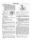
• Included withthis unit is a quick-connect fitting that you
attach to the water inlet, It can separate into two parts
a black male connector and an orange section that
contains an inlet screen. Make sure screen is clean.
Attach the quick-connect fitting to the lower plastic
fitting on the front of the pump (Fig. 4). The black male
connector is the side that you attach to plastic fitting
• Unravel high pressure hose and check that threads on
one end are properly covered with teflon tape. If tape
is not proper],/apphed, reapply it so threads are fully
covered, The tape seals the connection from hose to
gun and wand assembly_
• Attach fitting with teflon tape togun and wand assembly
(Fig. 3). You may want to sp)n gun or spin hose to
secure connection. Tighten with crescent wrench.
• Attach the other end of the high pressure hose to metal
upper' fitting on pump. Tighten with crescent wrench.
END
FIG. ,3
rAPE
TO PLASTrc,
FITTING t
FIG. 4
CHECKLIST
o Check that fasteners are tight. Vibration during oper-
ation may loosen fasteners that are not tight enough_
• Checkfor proper hose connections (high pressure and
water supply) and for tight connections,
• Provide proper' water supply (not to exceed 140°F).
6