


Cold Drink Center Parts Manual List of Figures
August, 2003 i 3280033
List of Figures
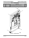
Section A: Exterior of Door................................................................................................ 1
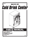
FIGURE 1: 328 Merchandiser ............................................................................................1
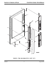
FIGURE 2: Trim - Millennia Style - Part 1 of 3 ...................................................................2
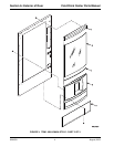
FIGURE 3: Trim - Millennia Style - Part 2 of 3 ...................................................................4
FIGURE 4: Trim - Millennia Style - Part 3 of 3 ...................................................................6
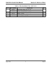
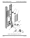
FIGURE 5: Trim - Standard Style ......................................................................................8
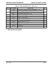
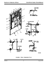
FIGURE 6: Door Assembly - Exterior ..............................................................................12
FIGURE 7: Display Assembly - Part 1 of 2 ......................................................................14
FIGURE 8: Display Assembly - Part 2 of 2 ......................................................................16
Section B: Interior of Door ............................................................................................... 18
FIGURE 9: Door Assembly - Interior ................................................................................18
FIGURE 10: Lock Bar Assembly - Standard Style .............................................................20
FIGURE 11: Lock Bar Assembly - Millennia Style .............................................................22
FIGURE 12: Door Lock and Handle Assembly - Standard Style .......................................24
FIGURE 13: Door Lock and Handle Assembly - Millennia Style ........................................26
FIGURE 14: Fluorescent Lamp Assembly & Ballast ..........................................................28
FIGURE 15: Service Light Assembly .................................................................................30
FIGURE 16: Service Light & Bracket Assembly (UK/France/Germany) ............................32
Section C: Miscellaneous Cabinet .................................................................................. 34
FIGURE 17: Common Cabinet - Rear ...............................................................................34
FIGURE 18: Base Plate Assemblies ..................................................................................36
FIGURE 19: Leg, Leveler, and Leg and Hinge Assemblies ...............................................38
FIGURE 20: Door Hinge Assemblies .................................................................................40
FIGURE 21: Interlock Switch and Bracket .........................................................................42
FIGURE 22: Capacitor And Bracket Assembly ..................................................................44
Section D: Cup Station..................................................................................................... 46
FIGURE 23: Cup Station Assembly ...................................................................................46
FIGURE 24: Miscellaneous Cup Station Components ......................................................48
FIGURE 25: Delivery Door Assembly ................................................................................50
FIGURE 26: Center Plate Assemblies ...............................................................................52
FIGURE 27: Mechanism And Canister Assembly - Short ..................................................54
FIGURE 28: Turret and Canister Assembly - Short ...........................................................56
FIGURE 29: Mechanism and Canister Assembly - Large ..................................................58
FIGURE 30: Turret And Canister Assembly - Large ..........................................................60
FIGURE 31: Mechanism Assembly ...................................................................................62
FIGURE 32: Cup Mechanism Mounting Bracket Assembly ...............................................64
FIGURE 33: Cup Ring Assembly .......................................................................................66