Page 8
Reference Manual
IQ-MC Modules
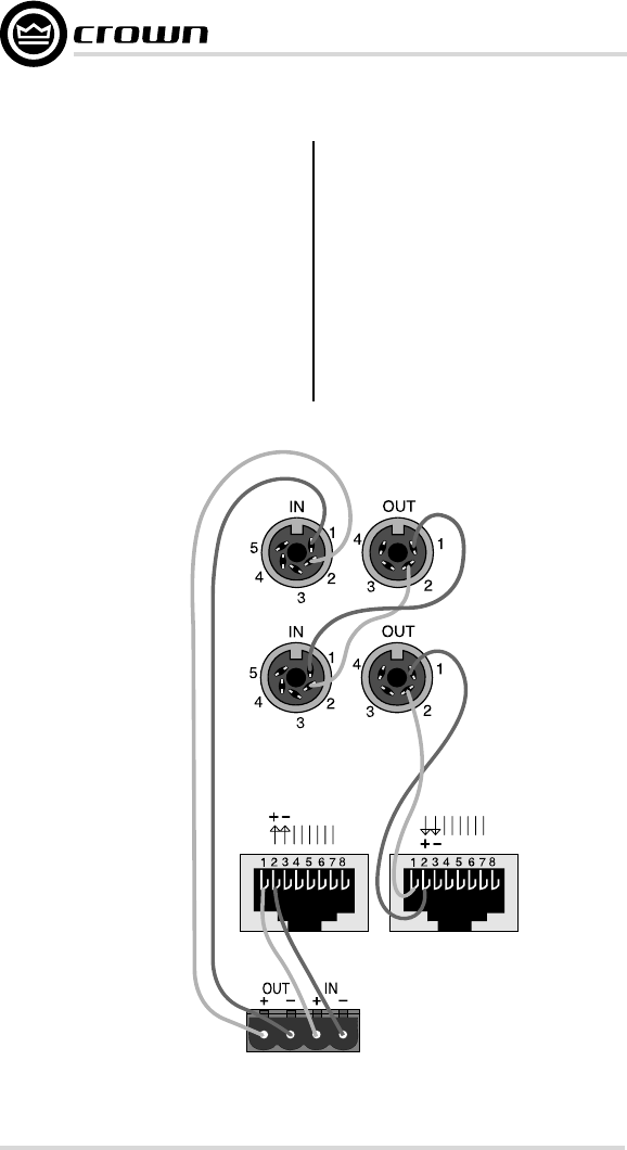
3.2 Install the Wiring
Connect the IQ-MC module to the IQ
system via the IQ Bus. The IQ compo-
nents in a IQ Bus loop are wired
sequentially. The loop begins and
ends with the IQ interface. The output
of one IQ component “loops” to the
input of the next and so on as shown
in Figure 3.2.
There are three different types of con-
nectors used for IQ Bus wiring on IQ
components. These include DIN con-
nectors, screw terminal plugs, and
RJ-45 connectors. The IQ-MC uses
RJ-45 connectors that accept stan-
dard RJ-45 plugs like the one shown
in Figure 3.6, allowing the use of in-
dustry-standard straight-thru type
network cables. The right RJ-45 con-
nector is used for input and the left RJ-
45 connector is used for daisy output.
Figure 3.2 Standard IQ Bus Wiring “Loops” from the Output to
the Input of each IQ Component (for Hub-Style IQ Bus wiring)
OUT
IN
IQ Interface
IQ Component
MC-IQ
IQ Component
