


7
Planning the Installation
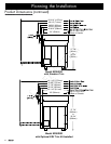
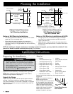
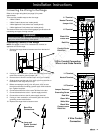
Cutout DIMENSIONS
F G
36” (914 mm)*
30” (762 mm)**
30
1
/
16
” (916 mm)*
* Recommended
** Minimum
24” Typ.
(610mm)
25” Typ.
(635mm)
F
G
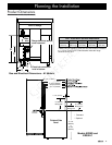
Cabinet Cutout Dimensions
Cabinet Layout
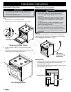
Carefully check the location where the range is to be
installed. For best performance, the range should be placed
away from drafts that may be caused by doors, windows and
heating and air conditioning outlets.
To reduce the risk of personal injury and to reduce
accumulated smoke in the room, Dacor strongly recommends
installing a range hood. A range hood should project
horizontally a minimum of five (5) inches beyond the face of
the cabinets.
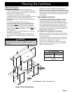
The range may be installed flush to the rear wall.
Dacor recommends installing a non-combustible material
on the rear wall above the range and up to the vent hood.
If a non-combustible surface is not installed, a backguard
or ERV raised vent must be installed. It is not necessary to
install non-combustible materials behind the range below the
countertop height.
Any openings in the wall behind the appliance or in the floor
underneath it must be sealed.
The minimum distance from the sides of the range above
the countertop to combustible side walls must be at least 10
inches.
WARNING
Do not operate the range without the backguard or raised vent
in place if the back wall is made of combustible materials. A fire
may result.
•
•
•
•
•
All dimensions shown are based on standard American
cabinets, 36 inches (914 mm) high at the finished countertop
by 24 inches (610 mm) deep, with a 25 inch (635 mm) overall
countertop depth. When installing the range into non-standard
cabinets, minimum clearances shown in the diagrams must
be maintained.
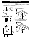
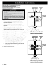
Gas and Electrical Service
The shaded area shown denotes the location of the gas
inlet and the electrical junction box/receptacle. This is the
recommended location. For replacement purposes, the
location of the existing utilities may be utilized provided they
do not interfere with the sides or rear of the range. Check
local building codes for permissible gas valve locations.
An external manual shut-off valve must be installed between
the gas inlet and the range for the purpose of turning on or
shutting off gas to the appliance.
The installation must allow for the following:
Access to the gas shut-off valve when the unit is installed.
Access to the remote circuit breaker panel or fuse box, when
the range is in place.
The gas supply piping, gas shut-off valve and the electrical
junction box or receptacle must be located so they do not
interfere with the range when it is installed.
The junction box and gas shut off valve must be located
so that the range can be pulled out for service while the
appliance remains connected.
•
•
•
•
•
•
•
All tolerances: +1/16”, -0 (+1.6 mm, -0)