


3
INSTALLATION INSTRUCTIONS
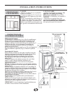
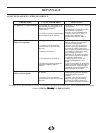
LOCATION
REQUIREMENTS
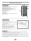
DO...
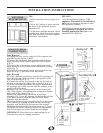
• Select a location with a strong, level
floor.
• Allow for 5 inches of space between
the back of the appliance and any
adjacent wall.
• Avoid direct sunlight and heat. Direct
sunlight may affect the acrylic coating;
heat sources nearby will cause higher
electricity consumption.
DO NOT...
• Use this appliance outdoors: This
appliance is intended for household use
only. Do not attempt to operate or store
this appliance outdoors.
• Build this appliance into an enclosure:
This appliance is designed for a Free-
Standing application only and is not
intended to be “Built-In”.
5 In.
5 In.
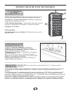
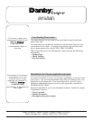
DOOR REVERSAL
INSTRUCTIONS
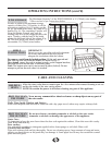
Door Removal
1) Unplug the wine cooler, empty all of its contents and
carefully lay the unit on its back.
2) Remove the adjustable foot located beside the lower
hinge assembly on the bottom right side of the cabinet
(Fig. 1).
3) Unscrew the two retaining screws holding the lower
hinge assembly to the bottom of the cabinet and set them
aside (Fig. 2).
4) Pull the door downward until it releases from the top
hinge pin (Fig. 3), and then set the door aside.
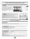
Door Reversal
5) Using a flathead screwdriver, transfer the top hinge pin
from the right side of the worktop to the opposite (left)
side of the worktop (Fig. 3).
6) Transfer the plastic cap located on the top left side of
the door to the opposite (right) side of the door (Fig. 4).
7) Set the door onto the cabinet and push it upward until
the top hinge pin is fully inserted into the opening on the
top left side of the door.
8) Remove the two retaining screws on the bottom left
side of the cabinet, and transfer them to opposite (bottom
right) side of the cabinet (Fig. 5).
9) Insert the bottom hinge pin on the lower hinge
assembly (Fig. 2) into the opening on the bottom left side
of the door, and then align the door and lower hinge
assembly with the cabinet.
10) Screw the lower hinge assembly (Fig.2) to the bottom
of the cabinet by aligning the holes in the lower hinge
assembly with the holes in the bottom of the cabinet.
11) Reinstall the adjustable foot removed in step 1 (Fig.1).
12) Ensure the door is squarely fitted to the cabinet and
that all fastenings are secure. Stand the unit upright.
IMPORTANT: Allow the unit to stand upright for at
least one hour prior to starting operation.
Top Hinge Pin
A. Top Hinge Pin
A. Plastic Cap
Lower Hinge Assy.
A. Hinge washer
B. Bottom hinge pin
C. Screw washers
D. Screw gaskets
E. Screws
A. Screw washers
B. Screw gaskets
C. Screws
Adj. Foot