5
INSTALLATION
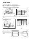
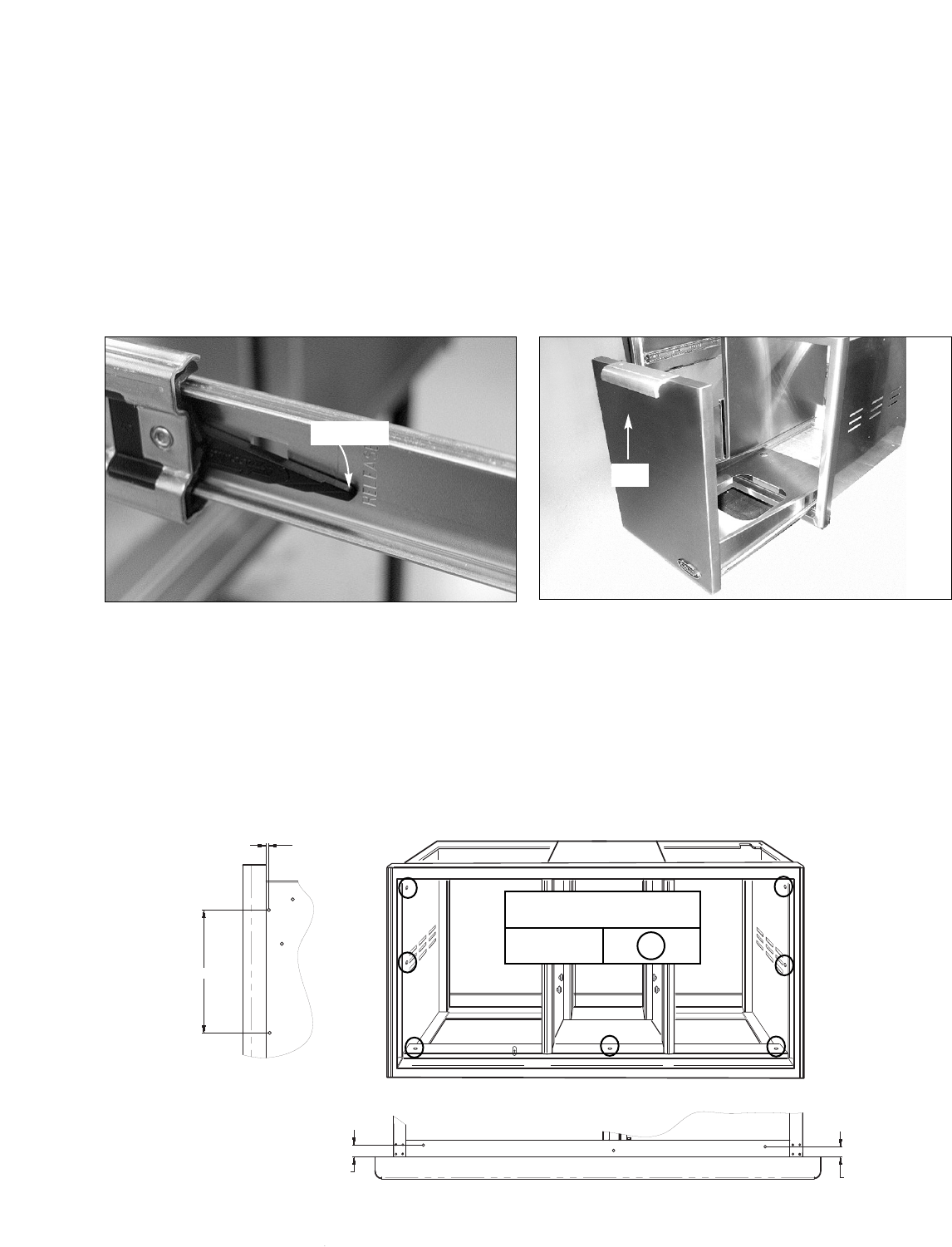
Fig. 7
REMOVING DRAWERS
1. Once the unit has been inspected, remove the left drawers by pulling them out until their slider latch is visible.
C
arefully push the latch down on the left side while pulling up on the right side and pull the drawers completely
out of the frame (Fig. 7).
2
. To remove the LP tank drawer on the right, pull the drawer out and lift the end by the handle to disengage the
rollers (Fig. 8).
3. To prevent damage to surfaces, place the drawers on a stable surface on a protective towel or tablecloth.
SLIDE IN FRAME AND MOUNT TO SUPPORT STRUCTURE
1. With the help of an assistant, lift the unit off of the pallet and slide it into the cabinet cutout. Adjust for level and
fit.
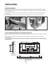
2 Locate mounting holes on the frame (Fig. 9 and views). Secure the unit using screws suited for the type of
cabinet material.
NOTE: Depending on the wall thickness and location of mounting holes, an additional board may be required to properly
receive the screws.
Fig. 9
Slider latch
Fig. 8
Lift
3/16"
TO 1/2"
8"
VIEW SHOWING HOLES ON
LEFT AND RIGHT SIDES
AVAILABLE FOR MOUNTING
3/4"
3/4"
VIEW SHOWING HOLES ON TOP AND BOTTOM
OF FRAME AVAILABLE FOR ADDITIONAL SUPPORT
MOUNTING SCREWS
(not provided)
L
OC
ATIONS


