


3
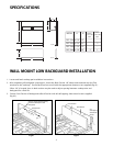
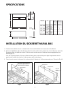
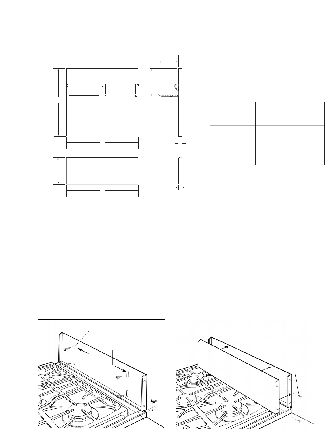
SPECIFICATIONS
B
A
8-3/4 "
12 "
B
A
1-5/16 "
1-5/16 "
MODEL
AB
BGC-1236
BGC-3036
BGC-1248
BGC-3048
-
-
2
-
-
-
2
1
RACK
(16-5/8")
QTY.
RACK
(13-5/8")
QTY.
35-7/8"
35-7/8"
47-7/8"
47-7/8"
12"
30"
12"
30"
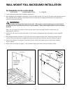
WALL MOUNT LOW BACKGUARD INSTALLATION
1. Locate and level cooktop per installation instructions.
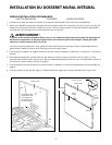
2. After unpacking all backguard system parts, locate the Back Section 1/8” above and centered over the Trim
attached to the cooktop.* Secure Back Section to wall with the appropriate fasteners (not supplied)(fig. 01).
*After 1/8” is located, slots in back section may be used to adjust spacing between cooktop trim and
backguard for a flush fit.
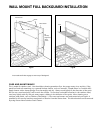
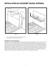
3. Secure Front Section of backguard to Back Section with #8 self-tapping sheet metal screws supplied
(fig. 02).
# 8
Self-tapping
sheet metal
screws
Back Section
Back Section
Front Section
Trim
Slots to choose desired spacing
between Cooktop Trim and
Backguard.
Fig.01 Fig.02
16”for 30”
36”for 36/48”