4
Under - counter
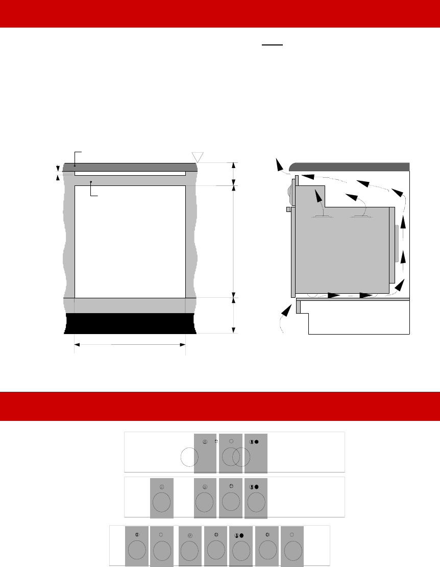
Installation for model 600
Worktop
32mm - 48mm thick
Vent
gap
at
front
only
100
590
Aperture
(210)
Floor
Datum
900
565 Aperture
Top filler piece
Typical section showing
ventilation requirements
A
perture
590 H x 565 W x 570 D
6
+
_
3
0
+
_
3
0
+
_
3
0
•
N
ote: The oven cavity must vent through the front only. Avoid gaps between the cavity
sides and the underside of the worktop
•
Insert the oven into the cupboard.
•
Open the door to expose the fixing holes in the side trims.
•
Secure the oven by 4 countersunk screws (fasteners are not supplied ).
•
The hob should be installed in a ventilated cupboard fitted with a sturdy worktop .
•
Secure the hob using the fixing brackets provided.
The control panel
600 STE
MULTIFUNCTION
600 SMW
600EMBW
MULTIFUNCTION
WITH WARMING
DRAWER
600 UMS
MULTIFUNCTION
1
1
1
2
2
2
3
3
3
4
8
7
6
5
1=OVEN THERMOSTAT. 2= MULTIFUNCTION SELECTOR. 3= RINGER TIMER. 4= WARMING DRAWER.
5= LEFT FRONT PLATE. 6= LEFT BACK PLATE. 7=RIGHT BACK PLATE. 8=RIGHT FRONT PLATE.


