


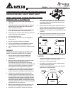
MODELS
SIG80L / SIG110L / SIG110HL / SIG110D
L
Page 2.
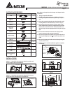
SUPPLIED ACCESSORIES
Part name Appearance Quantity
Grille 1
Tapping screw
(ψ
4x25)
4
Screw
#8-32x1/4”
4
Grille bracket screw
(M4x6)
1
Grille screw
(M4x30)
2
Nut
(M4x4.4)
1
Duct connector 1
Duct screw
(M4x12)
1
Suspension bracket I
13 (318.5)
2
Suspension bracket II
13”(318.5)
2
Grille bracket
1
GU24 base bulb lamp
(26W)
1
E12 base bulb lamp
(4W)
1
Inches (mm)
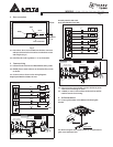
INSTALLATIONS
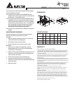
Attach Duct Connector
Option 1. Attach the duct connector from the outside, and
secure using the duct screw (M4X12).
Insert tab into
slot in housing
Duct screw(M4X12)
from Parts Bag
Option 2. Attach the duct connector from the housing can
inside, and secure using the duct screw (M4X12).
Pull existing ductwork
into Housing
Insert tab into slot
in Housing
Duct screw(M4X12)
from Parts Bag
Note: Remove the tape from the damper and adaptor before
installation.
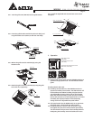
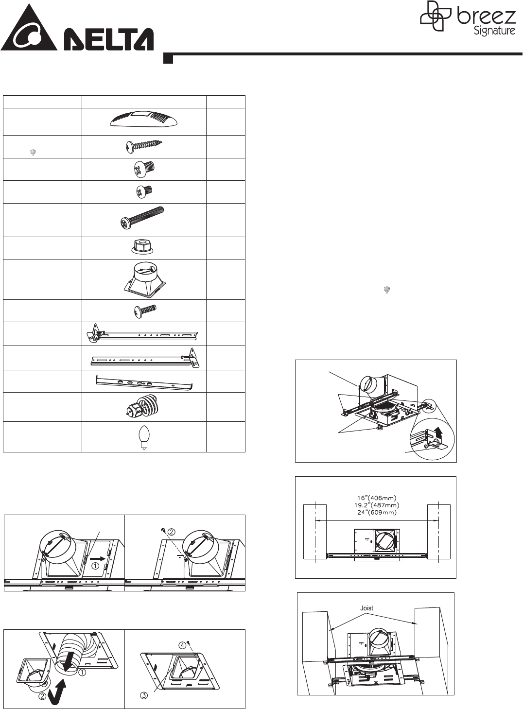
1. Using suspension brackets
1-1. Sliding suspension brackets are available to allow the
housing to be positioned between joists up to a span of
1-2. Insert the suspension brackets into the channels on the
housing. Make sure the tabs face up as shown. (Fig. C)
1-3. Extend the suspension brackets to t the width of the
joists. Hold the fan in place by wrapping the suspension
bracket tabs around the bottom of the joist.
Make sure
the fan body is level and perpendicular to the joist. (Fig. D
& E)
1-4. Ensure that the distance between the ceiling and fan
body is appropriate for mounting the grille.
1-5. Secure the suspension brackets to the joists with nails or
by using the tapping screws (ψ
4x25) through holes near
nails.
1-6. Secure the suspension bracket to the fan body using the
screws (#8-32 x 1/4").
1-7. Follow steps 2 to 6 of the installation guide to complete
installation.
Suspension
Bracket II
Suspension
Bracket I
Body
Tab
Fig. C
Fig. D
Fig. E
9.68”
24”.