


SUPPLIED ACCESSORIES
Part Name Appearance Quantity
Grille 1
Long Screw
(M4x25)
6
Screw
(M4x12)
3
Suspension Bracket
(155mm)
1
Suspension Bracket
(300mm)
1
Suspension Bracket
(355mm)
1
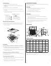
INSTALLATIONS
A. Install with Wood Frame
Model No. VFB25AD VFB25AC VFB25ACH VFB25AEH VFB25ADH VFB25AX
Install Dim.
(mm)
260 x 260 260 x 260 260 x 260 260 x 260 260 x 260 260 x 260
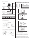
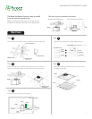
1. Body Installation
1-1. Construct the wood frame (not provided) with 30mm squarebar
and attach it to the ceiling joist.
1-2. Attach the duct connector to the wood frame with taping screw.
1-3. Insert the body into the wood frame and connect it to the duct
connector. Secure the body on wood frame with taping screws.
1-4. Follow step 6 to 9 of installation to complete the installation work.
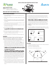
B. Install with Joist
1. Choose the installation type according to the gure as below:
Spacing A on
Center Joists
Insert Suspension
Bracket
12 inches Refer to Fig. D-01, E-01
16 inches Refer to Fig. D-02, E-02
19.2 inches Refer to Fig. D-03, E-03
24 inches Refer to Fig. D-04, E-04
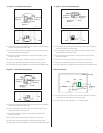
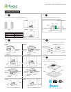
2. Type I – 12 inches between joists
2-1. Insert the suspension bracket into the bracket cover of adaptor
side and the back of the fan body.
2-2. Insert the fan between joists. Make sure the fan body is level
and perpendicular with the joist.
2-3. Ensure the distance between ceiling and fan body for the
thickness of grille.
2-4. Secure the suspension bracket to joists by using screw.
2-5. Secure the suspension bracket to fan body by using screw.
2-6. Follow step 6 to 9 of installation to complete the installation work.
Wood Frame
Wood Frame
Duct Connector
Taping Screw
Taping Screw
Body
Joist
A
2
Fig. C-02
Fig. C-01
Suspension
Bracket I
Suspension
Bracket II
Body
Joist
Joist
Fig. D-01
Fig. E-01
Inches (mm)Inches (mm)Inches (mm)Inches (mm)
Inches (mm)Inches (mm)