


www.desatech.com
118197-01C8
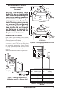
Therearetwobasictypesofdirect-ventin-
stallation:
• HorizontalTermination
• VerticalTermination
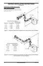
IMPORTANT: Horizontalsquareterminations
requireonlyinnerportionofwallrestop.Hori-
zontalinstallationsusingroundterminationrequire
exteriorportionofwallrestop(seeFigure14,
page10.
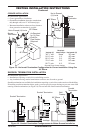
1. Setthereplaceinitsdesiredlocationanddeter-
minetherouteyourhorizontalventingwilltake.
Donotsecurethereplaceuntilallventinghas
beeninstalled.Someinstallationsrequiresliding
thereplaceinandoutofpositiontomakenal
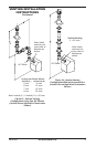
ventingconnections.Figures14through18on
pages10through12showdifferentcongura-
tionsforventingwithhorizontalterminationthat
willhelpyoudecidewhichapplicationbestsuits
yourinstallation.Checktoseeifwallstudsor
roofraftersareinthepathofyourdesiredvent-
ingroute.Iftheyare,youmaywanttoadjustthe
locationofthereplace.
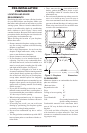
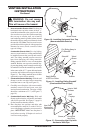
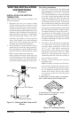
2. Directventpipesectionsandcomponentsare
designedwithspecialtwist-lockconnections.
Thefemaleendsofthe
pipeshavelockinglugs(indentations).These
lugswillslidestraightintomatchingslotson
themaleendsofadjacentpipes.Pushpipesec-
tionstogetherandtwistonesectionclockwise
approximatelyone-quarterturnuntilthesections
arefullylocked(seeFigure8).Note:Horizontal
runsofventmustbesupportedeverythreefeet.
Usewallstrapsforthispurpose.
3. Usea45°elbowtoconnectventingsystem
toreplaceuecollar.Theelbowisdesigned
tobetwist-lockedontothefluecollaras
describedinstep2.IMPORTANT:Donot
attempttoalterthecongurationoftheelbow
bycutting,twisting,bending,etc.
4. Assemblethedesiredcombinationofpipeand
elbowstothereplaceuecollar.Ifthereare
longportionsofventingrun,pre-assembled
pipesectionsmaybeinstalledassubassem-
bliesforconvenience.
VENTINg INSTALLATION
INSTRUCTIONS
Continued
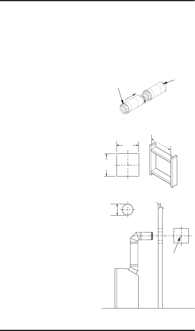
Figure 8 - Vent Pipe Connections
Female
Locking
Lugs
Male
Slots
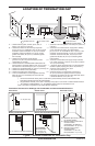
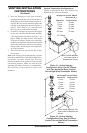
(Framing
Detail)
10
3
/
4
"
10
3
/
4
" Inside Framing
10
3
/
4
"
8
1
/
2
"
Vent
O
pening
Combustible Wall
Vent Opening
Noncombustible Wall
Figure 9 - Vent Opening Requirements
Center of
Hole
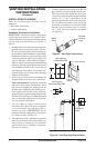
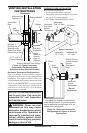
5. Carefullydeterminethelocationwherethevent
pipeassemblywillpenetratetheoutsidewall.
Thecenteroftheholeshouldlineupwiththe
center-lineofthehorizontalventpipe.Markthe
wallfora10
3
/4"x10
3
/4"squarehole.Cutand
framethesquareholeintheexteriorwallwhere
theventwillbeterminated.Ifthewallbeing
penetratedisconstructedofnoncombustible
material,suchasmasonryblockorconcrete,
a 8
1
/2"holewithzeroclearanceisacceptable
(seeFigure9).