GAS EQUIPMENT
Flue Top and Baffle
The flue baffle is suspended from the
top, and
must be
in position in the central tube of the
cooling
unit.
The Flame Failure Safety Device
The feeler of the
thermo
couple shall reach in over two
slots of the burner. To replace the
thermo
couple pro-
ceed as follows:
1.
Remove the cover.
2.
Unscrew plug and pull thermo-couple straight out.
3.
Remove spring.
4.
Pull out thermo-couple sideways from burner
housing.
5.
Bend the new thremo-couple to the same shape
as the old one.
6.
Reassemble in reverse order. Check that feeler
has been correctly refitted in relation to burner.
7.
Mount plug, taking care not to damage the threa-
ded hole in the aluminum cap of the housing. The
plug must be properly tightened to the valve hou-
sing to ensure good contact between the
thermo
couple and the magnetic coil within the housing.
The Thermostat
The refrigerator is equipped with a thermostat which
is regulated by turning the knob to different settings in
order to obtain the desired controlled cabinet tempe-
rature.
At
OFF
Under normal operating conditions the
thermostat valve remains closed and the
burner is running continuously at the by
pass rate, just enough to keep the burner
lit.
At MAX
The thermostat valve remains open and
the burner is running
continously
at full gas
rate. Lowest cabinet and freezer tempera-
tures are obtained at this setting.
Between these two extremes of the dial various con-
trolled temperatures can be obtained, by turning the
thermostat knob to a suitable position. The closer to
MAX the lower the temperature. As soon as the requi-
red cold temperature inside the cabinet is reached.
The thermostat cuts the burner main flame leaving the
by-pass flame to keep safety valve open.
The Igniter
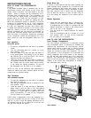
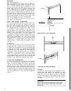
The refrigerator is fitted either with a piezo igniter (see
fig.1)
or an automatic reigniter (fig. 2 and 3) which
does not normally need any
maintenace.
If the igniter
does not work properly contact an authorized service
point
ELECTRIC
EQUIPMENT
Cartridge heater
The refrigerator is equipped also for electric opera-
tion. Many models are eqiupped for both 120 Volts A
C and 12 Volts D C operation. The heat necessary for
the operation of an absorption type cooling unit is
supplied by an electric cartridge heater mounted on a
pocket of the boiler system. To replace the heater first
of course check that the wall plug is disconnected. If
the refrigerator is equipped also for 12 Volts D C ope-
ration make sure that the 12 V leads are disconnected.
Then proceed as follows:
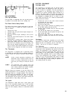
1.
Remove the cover of the main control structure
by loosening the two screws
2.
Disconnect the heater leads
3.
Pull off the metal hose
4.
With a pair of pliers unfold the lug holdning the lid
of the boiler casing and open the lid
5.
Remove some insulation wool so that the heater
is accessible
6.
Turn and ligt the heater out of its pocket
7.
Fit the new heater into the pocket and pull on the
hose around the leads
8.
Connect the leads and put on the plastic cover
9.
Reset the insulation and close the lid of the boiler
casing
The Switch
The electronic control also comprises an on-off switch
operated by the selector knob at the front panel. The
switch has two “on” positions, one for 120 Volts A C
(ELEC.
)
and one for 12 Volts D C operation.
The Thermostat
The electric thermostat is combined with the gas ther-
mostat and is thus operated by the knob B at the front
panel. The temperature in the refrigerator can be re-
gulated by turning the thermostat knob. Although the
exact setting is not critical choose a setting at which
the frost which gradually forms on the cooling evapo-
rator is just maintained in dry condition. It will be ne-
cessary to turn the thermostat knob closer to MAX
when the ambient temperature becomes higher or the
load unusually heavy. If less cooling is required a lo-
wer setting should be chosen.


