


13
B. Check all connections in the LP gas system (at the
back of the refrigerator) for gas leaks. The LP gas
supply must be turned on. Apply a non-corrosive
bubble solution to all LP gas connections.
The appearance of bubbles indicates a leak and
should be repaired immediately by a QUALIFIED
SERVICEMAN WHO IS FAMILIAR WITH GAS SYS-
TEM AND REFRIGERATORS.
DO NOT use a wire or pin when cleaning the burner
jet as damage can occur to the precision opening.
This can cause damage to the refrigerator or create
a fire hazard.
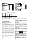
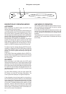
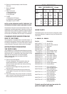
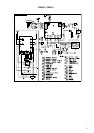
FIG. 13
Clear blue color
of flame
! WARNING
10. Reinstall burner, being careful that the end of the
burner fits into the slot on the burner bracket. Check
to make sure slots are centered under the flue tube
and the thermocouple is positioned properly (tip of
thermocouple extends over two slots of burner).
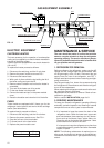
11. Be sure to reconnect the wire to high voltage elec-
trode. Check the electrode for proper location and
gap. (See FIG. 14).
12. Turn on manual gas shutoff valve and check all fit-
tings for leaks with soapy water.
13. Connect 120 volt power cord to the outlet and re-
connect or turn on the 12 volt DC power.
14. Check LP gas safety shutoff. See page 6.
TROUBLESHOOTING
The Refrigerator Does Not Cool Properly
A. Burner jet clogged.
Clean. (See Section Maintenance & Service, item 2.
Periodic maintenance, Paragraph E item 1-14.
B. Check level of refrigerator.
C. Venting problem.
Restriction in air flow across cooling unit.
D. Heavy frost buildup on evaporator fins.
Defrost.
E. Flue baffle not inserted properly in flue tube.
F. Burner dirty.
Clean. (See section Maintenance & Service, item 2.
Periodic Maintenance, Paragraph E item 1-14).
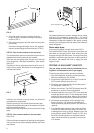
G. LP gas pressure low at burner.
Set main regulator so pressure does not drop
below 11 inches of water column at pressure test
port. (See FIG. 12).
! WARNING
DO NOT use a flame to check for gas leaks.
C. Check the control system by connecting/disconnect-
ing 120 volt AC power, start/stop the engine, etc.
Compare the operation with the operation described
in section Operating Instructions.
D. The LP gas pressure should be checked and the main
regulator readjusted if pressure is incorrect. The cor-
rect operating pressure is 11 inches of water column.
The correct place to take the LP gas pressure is at
the test port just ahead of the burner jet. (See FIG. 12).
E. Inspect the flue baffle. It should be reasonably clean
and free of soot. Heavy soot formation indicates im-
proper functioning of the burner. The flue and burner
both require cleaning in the following manner:
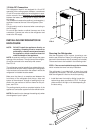
1. Unplug the refrigerator power cord from the 120 volt
AC outlet. (See FIG. 3).
2. Disconnect or shut off the 12 volt DC power to the
refrigerator.
3. Turn manual shutoff valve to OFF. (See FIG. 1 & 12).
4. Remove cover from the burner housing. (See FIG. 1).
5. Disconnect the wire from the high voltage electrode.
6. Remove the burner mounting screw and remove the
burner assembly. (See FIG. 12).
7. Remove the wire and flue baffle from the top of flue
tube. Clean the flue from the top using a flue brush.
Blowing compressed air into the flue will not properly
clean soot and scale out of the flue tube. Replace
the flue baffle.
8. Clean burner tube with a brush. Blow out burner with
compressed air.
9. Before removing burner jet, clean burner area of soot
and scale that fell out of flue tube. Remove the burner
jet. Soak the jet in wood alcohol and blow it out with
compressed air. Reinstall and tighten burner jet.
NOTE: The color of the flame shall be clear blue over
the slots of the burner. (See FIG. 13).
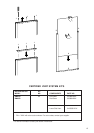
FIG. 14
Electrode
Burner tube
1/8” to 3/16”
(3-5 mm)