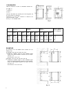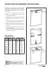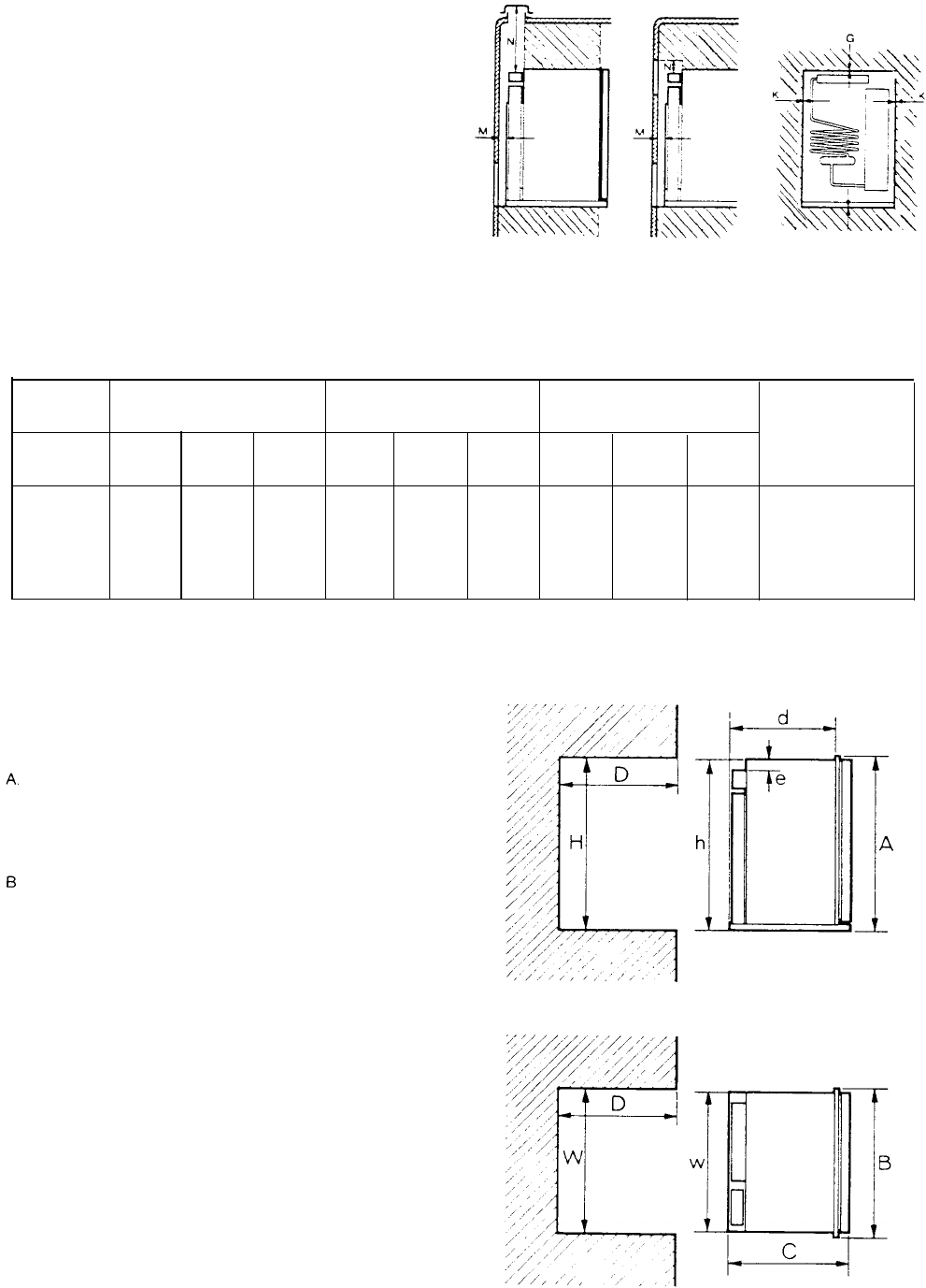
CLEARANCES
Minimum clearances in inches to combustible
materials
are
G: Top 0
K: Side 0
L: Bottom 0
M: Rear 1
Clearance M between the
rearmost
part of the
refngerator
and
the wall behind the refrigerator
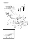
Clearance N on top of the condenser is related to the
minimum’ventilation height
See Fig 11 and examples below
Fig. 11
Refrigerator
Overall
Installation
Recess
Distance between
model
dimensions
dimensions
dimensions
top of condenser to
top of refrigerator
Height
Width
Depth
Height
Width
Depth Height Width
Depth
A
B
C
h
W
d
H
W
D
e
RM360 30 3/8 21 11/166 22
1/16 29 9/16 20 1/4 20 3/16 29 3/4 20 1/22 21 3/16 1 1/4
RM460 32 15/16623 24 11/16632 1/8 21 9/16 22 3/4 32 5/16 21 13/16 23 3/4 1 1/4
RM660 40 13/16623 24
11/166 40 21 9/16 22 3/4 40 3/16 21 13/16 23 3/4 1 1/4
RM760 52 23 24 11/166 51 3/16 21 9/16 22 3/4 51 3/8 21 13/16 23 3/4 1/8
RM1300 57 15/166 24 15/166 24 11/16 57 1/8 23 7/16 22 3/4 57 1/2 23 13/16 23 3/4 1/8
EXAMPLES
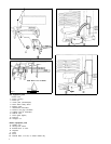
The clearance N for the RM360 model IS derived at in the
following way
Installation with upper and lower side vents
N=Minimum ventilation height 37 minus installation height
29
9/1
6 plus distance between condenser top and
refrige-
rator
top 1 1/4
N=37-29 9/16+1 1/4=8 11/16
Installation
with
roof vent and lower side vent
N=Minimum
ventilation height 31 minus installation height
29
9/1
6 plus distance between condenser top and refrigerat-
or top 1 1/4 plus distance between roof surface and roof
vent cap 5 1/4
N=31-29 9/16+1 1/4+5 1/4=7 15/16
Fig. 12
8


