


14
DOMETIC® RM7030/RM7732
Refrigerators
DIAGNOSTIC SERVICE MANUAL
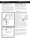
With the mode switch (?) NOT depressed: A
reading would NOT be indicated.
NOTE: If the check on AC mode lamp and switch is
not correct, verify the wire harness has continuity. If
wire harness is good, replace the upper circuit
board.
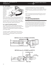
G. DELAY MODE LAMP AND SWITCH
NOTE: The following checks should be made on the
upper circuit board and harness assembly BEFORE
replacing the upper circuit board or wiring harness.
The checks are to be done with the wiring harness
REMOVED from the lower circuit board, and the
OFF-ON switch turned to "ON".
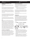
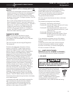
With the mode switch (?) manually depressed:
Resistance should be indicated between the brown
terminal on the 10-pin connector (negative [] lead
from meter) to the yellow terminal on the 7-pin
connector (positive [+] lead from meter). The proper
resistance is approximately
26,000 ohms.
With the mode switch (?) NOT
depressed: A reading would NOT
be indicated.
NOTE: If the check on the delay
mode lamp and switch is not
correct, verify the wire harness
has continuity. If wire harness is good, replace the
upper circuit board.
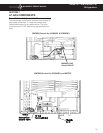
H. GAS MODE LAMP AND SWITCH:
NOTE: The following checks should be made on the
upper circuit board and harness assembly BEFORE
replacing the upper circuit board or wiring harness.
The checks are to be done with the wiring harness
REMOVED from the lower circuit board, and the ON-
OFF switch turned to "ON".
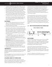
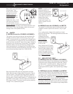
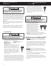
With the mode switch (?) manually depressed:
Resistance should be indicated between the brown
terminal on the 10-pin connector (negative [] lead
from meter) to the green terminal
on the 7-pin connector (positive [+]
lead from meter). The proper
resistance is approximately 26,000
ohms.
With the mode switch (?) NOT
depressed: A reading would NOT
be indicated.
NOTE: If the check on gas mode lamp and switch is
not correct, verify the wire harness has continuity. If
wire harness is good, replace the upper circuit
board.
YELLOW
BROWN
10 Pin7Pin
BROWN
10 Pin7Pin
GREEN
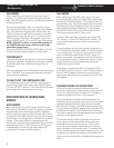
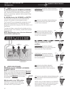
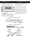
I. GAS FLAME WARNING LAMP:
NOTE: The following checks should be made on the
upper circuit board and harness assembly BEFORE
replacing the upper circuit board or wiring harness.
The checks are to be done with the wiring
harness REMOVED from the lower circuit
board, and the OFF-ON switch turned to
"ON".
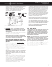
Measure resistance between the brown
terminal on the 10-pin connector (negative
[] lead from meter) to the black terminal on
the 10-pin connector (positive [+] lead from
meter). The proper resistance is approxi-
mately 22,000 ohms.
NOTE: If the check on gas flame warning lamp is not
correct, verify the wire harness has continuity. If wire
harness is good, replace the upper circuit board.
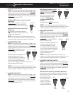
J. RM7030 (Product No. 921890401) and RM7732
NOTE: The PAL tester will allow for proper testing of the
integrity of the upper and lower circuit boards. PAL is
available from your Dometic parts distributor.
NOTE: Each of the following tests should be done
according to pin locations. The wire colors may
vary.
With main ON/OFF switch on display panel in OFF
position:
Check for DC voltage at Plug 1, Terminal 4 and terminal
5 negative () DC on the lower circuit board. If no
voltage, then check fuse condition. Replace if blown.
Check for DC voltage between J4 and J10 terminals on
the lower circuit board. If fuse is good and there is
battery voltage at J4, remove and replace lower circuit
board.
Next, check for DC voltage at the upper circuit board
between terminal 4 (orange or white wire) and terminal
3 (black wire) which is negative () DC. If no voltage,
and your previous check proved voltage at the lower
circuit board between these wires, replace the cable
assembly. If DC volts are present, proceed to the next
check.
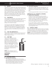
BLACK
BROWN
10 Pin
UPPER CIRCUIT BOARD