15
USA
5938 035 01
- OVEN level C -
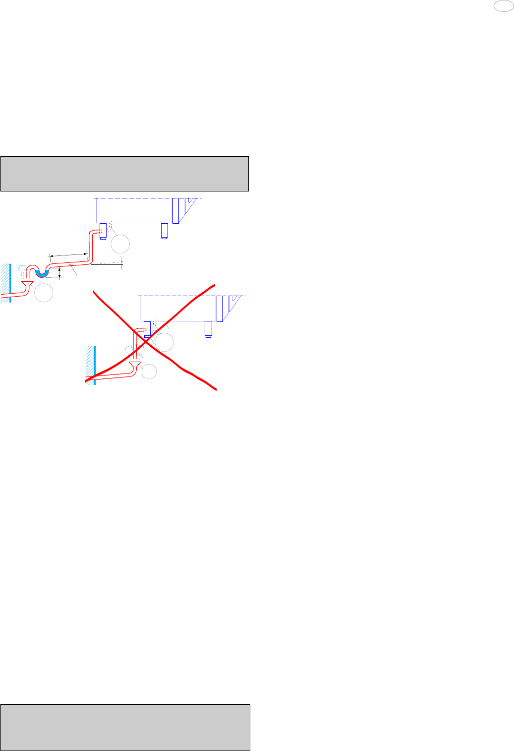
Connect drain fitting “C” to a drain pipe of the same diameter
which is between 0.5 and 3 metres in length and is resistant to
temperatures of at least 100°C. The drain pipe must be siphoned
(height 80 mm) to an open drain “O” (“Air-Break”) or floor grating
(see Fig. 12b) in order to prevent any back-flow from the sewage
system from reaching the piping inside the oven or oven chamber.
Check the hoses and elbows on metal pipes for kinks or pinching
along the entire drain line and make sure the drain line has a
minimum gradient of 5° to prevent water from collecting inside
the system.
Important: The drain system must be installed so that any
vapours from the open drain do not enter the aeration vents
under the appliance.
OK
min 5°
C
AIR-BREAK
T max = 100°C
max 3m
0,08 m
min 0,5m
O
C
AIR-BREAK
O
KO
5. SAFETY DEVICES
The appliance is fitted with the following safety devices:
- Fuses (see electrical circuit diagram) located behind the control
panel.
To change a fuse unscrew and remove the retainer cap and
replace the blown fuse with an identically rated component; the
fuse rating value is specified on the relative dataplate.
- Oven chamber safety thermostat with manual reset, located
behind the control panel; when this device trips, convection
heating power is disconnected.
Notice: CONTACT YOUR AUTHORIZED SERVICE COMPANY
TO PERFORM MANINTENANCE AND REPAIRS.
- Automatic reset thermal protection inside the cavity fan
motor: this device trips in the event of overheating of the cavity
fan motor; this cut-out protects the appliance by disconnecting
the power supply to the main PC board and an error message is
display EFUN.
6. OPERATION CHECK
- Switch on the appliance in accordance with the following
section "Instructions for use".
- With the aid of the Instruction Booklet, explain operation,
routine maintenance, and cleaning to the user.
Important:
- Exercise due care since certain areas of the oven exterior
become hot during use.
- Do not cover the exhaust outlets on top of the appliance.
7. SERVICING
All components requiring routine maintenance may be easily
reached by opening the control panel, removing the left side
panel, or removing the rear panel.
Danger: Live voltage is present with panels removed and unit
switch on. Exercise extreme caution when work with livevoltage.
NOTICE: Using any parts other than OEM original spare parts
relieves the manufacturer of all warranty and liability.
8. TROUBLESHOOTING
Malfunctions may occur even when the appliance is used
correctly.
Oven chamber heating not started or inefficient. Possible
causes:
- Oven chamber temperature limit switch tripped
- Damaged heating elements
- Damaged heating element contactor coil
- Damaged thermostat probe showing error “EPt1”.
- Damaged controller
- Fuse “F2” blown, see circuit diagram.
Steam production not started or inefficient.
Possible causes:
- Damaged heating elements
- Damaged heating element contactor coil
- Damaged controller
- Fuse “F2” blown
- No mains water supply
- Faulty boiler drainage outlet closing device
- Damaged water inlet solenoid valves (do not open)
Oven chamber temperature reading incorrect
Possible causes:
- Damaged electronic controller
- Thermostat probe damaged, dirty or interrupted, see error
“EPt1”.
Oven switches off
Possible cause:
- Fuse “F2” has blown due to damage of control circuit components.
Oven chamber lamp fault
WARNING: Switch off the appliance before changing oven
chamber lamps.
9. LAYOUT OF MAIN COMPONENTS
(All work inside the appliance must be carried out exclusively
by a trained installer authorised by the manufacturer)
Removing the control panel provides access to the following
components:
Danger: Live voltage is present with panels removed and unit
switch on. Exercise extreme caution when work with live voltage.
- Electronic circuit boards
- Oven chamber temperature limit thermostat
- Fuses
- Door microswitch
- Oven chamber lamp transformer
- Geared motor for the oven chamber pressure relief butterfly
valve.
WARNING: Before servicing unit switch off power at the main
circuit breaker and place a red tag on the breaker to indicate work
is being done on the circuit.
Remove the appliance left hand side panel to gain access to all
the other components.


