INSTALLATION INSTRUCTIONS
Page 8 62.9540.01_UL
4. GAS CONNECTION
The installation of the gas connection, as well as the laying of
the customer's gas line, is only to be carried out by an author-
ised specialist subject to the relevant national and local regula-
tions.
NOTE
• The gas appliance may only be installed in an adequately
ventilated location.
• Appliances are set up for natural gas. The type of gas, gas
pressure and gas category are entered on the specification
plate. Prior to connection, check that the appliance is set
up for the type of gas available on site. To do this, compare
the details on the specification plate with the existing gas
data.
• If this is not the case, the appliance must be converted or
adapted by the service personnel responsible to suit local
conditions. The following points should be noted:
- Has the appliance been tested for the new gas data?
- Conversion in accordance with the Service Manual.
- A new specification plate or a durable marking with the
new gas data must be affixed to the appliance.
4.1 CONNECTION
Gas-only appliances as well as combination electric and gas
appliances require a gas connection.
The gas connection is located under the appliance on the right
hand side. For all types the gas connection is NPT 3/4“.
The installation of a dirt trap in the gas supply line by the owner
is recommended.
After connection, all lines carrying gas must be tested for leaks
at operating pressure by painting with non-corrosive foam-
forming media, (e.g. soapy water or leak spray).
4.2 GAS PRESSURE
The current gas pressure should be measured at the Mertik
regulator with a liquid U-tube manometer (scale at least 0.1
mbar = 1 mm water column).
D Remove the control panel. The measuring nipple is located
in downwards direction at the gas supply pipe before the
two gas valves.
D Close off the mains gas leading to the appliance.
D The measuring nipple is provided at the left side of the reg-
ulator. The incoming pressure is measured in front, the out-
going pressure behind.
D Loosen the slotted screw (1 turn) in the measuring nipple.
Then connect the pressure gauge by attaching a flexible
tube to the nipple (out-side diameter 8 mm).
D Open the main gas leading to the appliance.
D Run all burners on the appliance at full output.
D Check whether the connection pressure is in permitted tol-
erance.
D Turn off the appliance again.
D Close the main gas valve.
D Retighten the slotted screw in the measuring nipple. Gas
pressure deviation tolerances are laid down by EN 203. If
the existing gas pressure is outside the given tolerances,
correct combustion can no longer be ensured. Compulsory
measures: pressure adjustment by the gas works or con-
version of the range by the service personnel. Please refer
to "Conversion to another gas type".
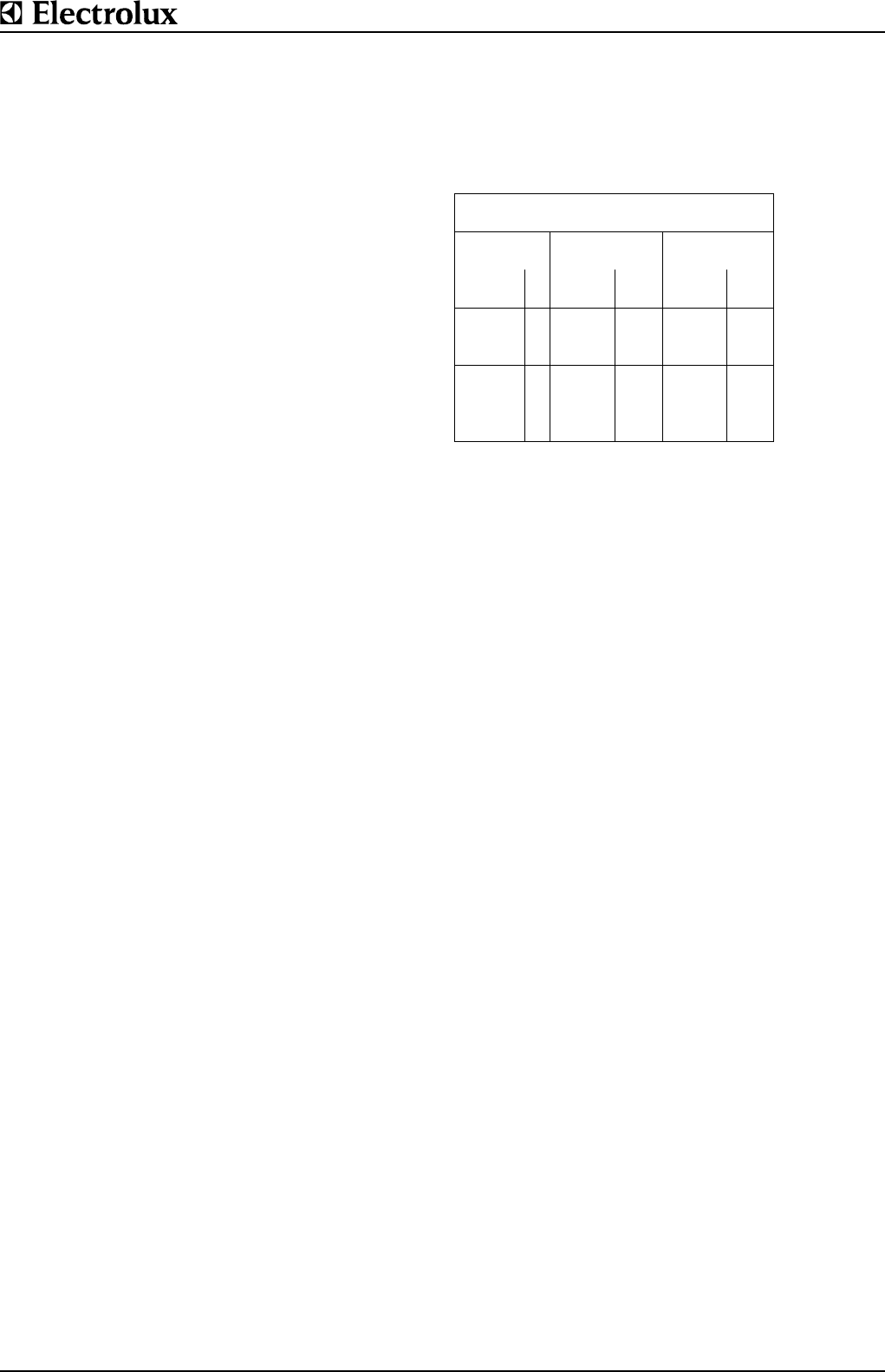
Gas pressure tolerances
Gas pressure variation tolerances are as
follows: mbar
Gas type Normal
pressure
Min.
pressure
inch
water g.
mbar inch
water g.
mbar
Natural gas A 7 17.4 3.5 8.7
USA
Liquid gas E 11 27.4 8.0 20
Propane
USA


