INSTALLATION INSTRUCTIONS
62.9677.01_UL Seite 7
2.1 FRONT PANELS (A) and (B)
D Unscrew screws (1 or 3). Also, in the case of a built-in oven,
unscrew screws (2 and/or 4) on the inside of the oven.
D Pull the panel away forwards and downwards.
2.2 CONTROL PANEL (C)
D Remove the knob.
D Loosen the screws underneath (1 / Fig.7a) and remove the
base plate.
D Loosen the screws (2 / Fig.7b) and 3 / Fig.7c)
D Remove the panel.
2.3 OVEN, STORAGE SPACE, HOT CABINET
D Remove panels A, B and C.
D Undo screws (5).
D Pull out element.
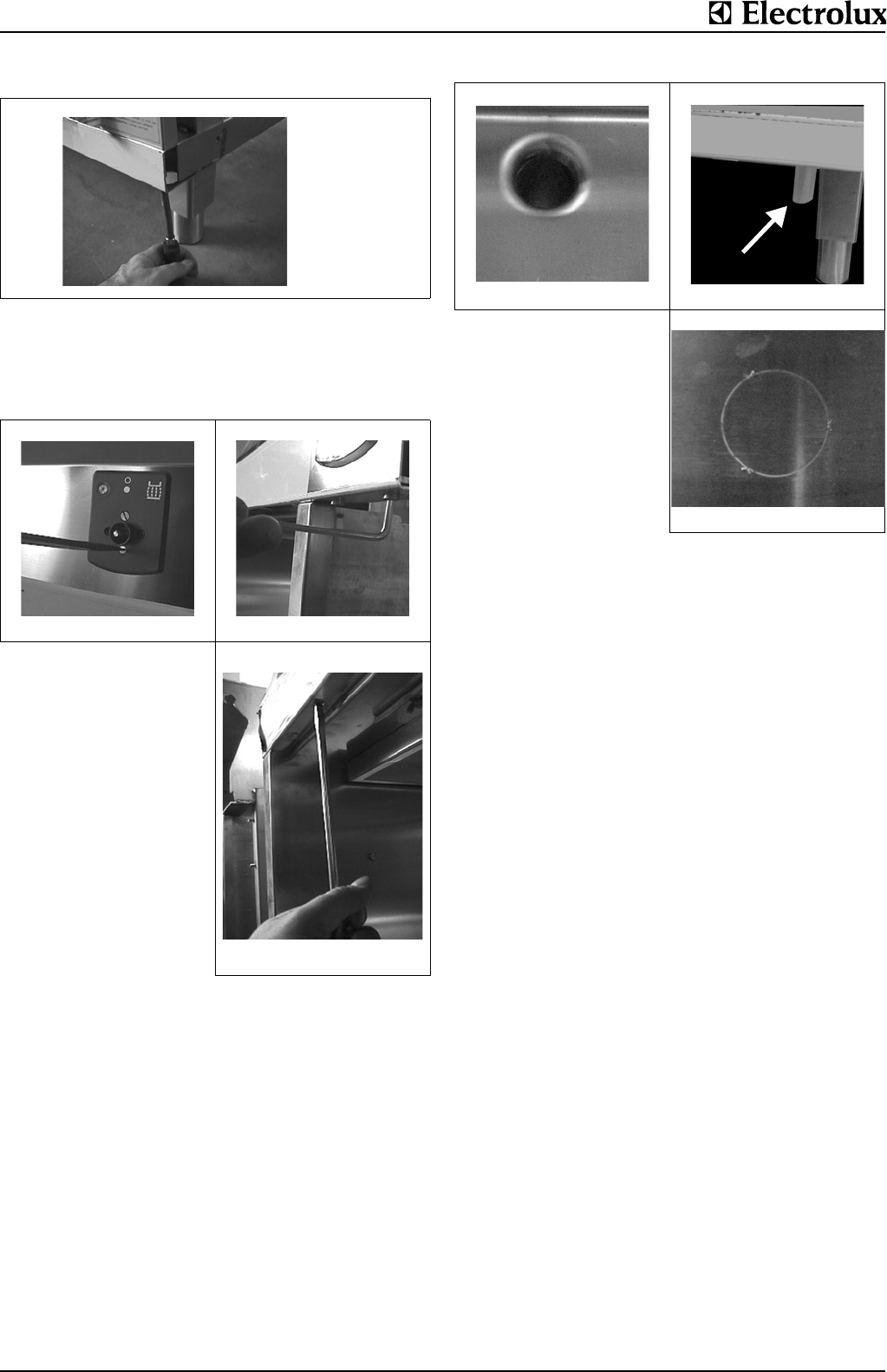
3. DOWNPIPE
Work surfaces with a downpipe (Fig.8a) have the downpipe
opening on the right-hand side of the appliance. A flexible sili-
con hose when installed in the standard manner ends under-
neath and to the right, 0.8“ (20 mm) behind the front of the
appliance (Fig.8b).
D Alternatively, the hose can be relocated to the rear and be
routed through other pre-cut openings (Fig.8c).
Fig.6 Front panel
ab
Fig. 7 Control panel
c
(1)
1
(3c)
(1)
1
(3c)
(2)
(3)
a
b
Fig. 8 Downpipe
c
1
(3c)
(1)
(3)


