


7
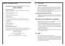
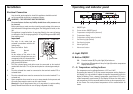
Operating and indicator panel
A. Light ON/OFF
B. Button ON/OFF
ON: Press the button (B). The pilot light (A) switches on.
OFF: Keep button (B) pressed until the pilot light (A) and the temperature
display switches off.
C - E. Temperature setting buttons
The temperature can be adjusted between -15°C and -24°C.
By pressing the button (C or E), the current temperature setting flashes on
the display. It is only possible to adjust the required temperature while the
display is flashing. To set a warmer temperature, press button (C). To set a
colder temperature, press button (E). The display will show the newly selec-
ted temperature for a few seconds and then return to the temperature insi-
de the freezer. The newly selected temperature will be reached within 24
hours.
A
B
C
DE
F
G
H
I
°C °C
A. ON/OFF light
B. Freezer button ON/OFF (green)
C. Temperature setting button (warmest)
D. Temperature display
E. Temperature setting button (coldest)
F. Fast freezing light (amber)
G. Fast freezing button
H. Alarm light (red)
I. Alarm reset button
18
Installation
Electrical Connection
Any electrical work required to install this appliance should be carried
out by a qualified electrician or competent person.
WARNING – THIS APPLIANCE MUST BE EARTHED
The manufacturer declines any liability should these safety measures not
be observed.
Before switching on, make sure the electricity supply voltage is the same as
that indicated on the appliance rating plate. The rating plate is inside, on the
left.
The appliance is supplied with a 13 amp plug fitted. In the event of having
to change the fuse in the plug supplied, a 13 amp ASTA approved (BS 1362)
fuse must be used.
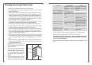
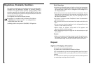
Important!
The wires in the mains lead are
coloured in accordance with the fol-
lowing code:
Green and Yellow Earth
Blue Neutral
Brown Live
As the colours of the wires in the
mains lead of this appliance may not
correspond with the coloured mark-
ings identifying the terminals in your
plug, proceed as follows:
1. The wire coloured green and yellow must be connected to the terminal
marked with the letter “E” or by the earth symbol or coloured green and yel-
low.
2. The wire coloured blue must be connected to the terminal marked “N” or
coloured black.
3. The wire coloured brown must be connected to the terminal marked “L” or
coloured red.
4. Upon completion there must be no cut, or stray strands of wire present and
the cord clamp must be secure over the outer sheath.
Warning! A cut-off plug inserted into a 13 amp socket is a serious safety
(shock) hazard. Ensure that the cut-off plug is disposed of safely.
D207
GREEN & YELLOW
13 AMP. FUSE
BROWN
CORD CLAMP
BLUE
13 AMP