


4. CONNECTING TO GAS
This appliance is designed to be installed with an appliance
flexible connection only. Supply piping should not be less than
R³/8. Connection is made to the Rc½ (½" B.S.P.) female
threaded entry pipe located just below the hotplate level on the
rear left hand side of the appliance. NOTE: ONLY LIQUID
SEALANTS TO BE USED WHEN INLET GAS PIPE IS
FITTED I.E.: DO NOT USE P.T.F.E. SEALANT TAPE.
Check for gas soundness after connecting the gas supply.
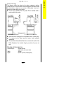
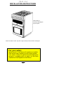
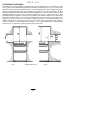
The gas bayonet connector must be fitted in the shaded area
indicated in Fig. 4. Take into account that it must be possible to
pull the appliance forward sufficiently. The hose must not get
caught on the stability bracket.
IMPORTANT: FLEXIBLE TUBING USED MUST COMPLY
WITH BS. 669 CURRENT EDITION.
L.P.G. FLEXIBLE CONNECTIONS MUST BE OF A TYPE
SUITABLE FOR L.P.G. AND CAPABLE OF OPERATION
UP TO 50 mbar AND TO CARRY A RED STRIPE, BAND
OR LABEL.
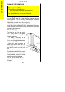
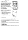
5. FITTING THE BATTERY
1. The battery is located on the left hand side of the front
plinth and can be viewed through a slot in the bottom
left hand corner of the front frame( Fig .5).
2. To gain access to the battery, open the main oven
door, rotate the battery holder clockwise.
3. Fit the battery AA size ensuring the positive, + terminal
is on the right hand side as shown in the diagram.
Return the battery to original position by turning it
anti-clockwise.
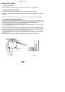
6. PRESSURE TESTING
1 The oven injector is used as a pressure test point.
Remove the oven furniture. Remove oven burner box retaining clips (one spring clip from each side) and
remove box front cover. Replace one clip back into the right hand side of the burner box.
Remove oven burner by removing the spring clip from the right hand side of the oven burner and slide
burner off injector, whilst easing it forward and taking care not to strain the F.S.D. phial.
2. Connect the pressure gauge to the oven injector.
3. Check the supply pressure by turning the thermostat on and one hotplate tap full on and light the
appropriate burner. The pressure should be either:-
(i) For Natural Gas 20mbar
(ii) For LP.Gas The pressure must be set to 28 mbar for use on butane or 37 mbar for use on propane.
4. Turn off the taps, disconnect the pressure gauge and replace oven burner and cover, ensuring that the
F.S.D. phial is correctly located into the bracket on the burner.
5. Check operation of oven.
7. CHECKING THE GRILL
Place the grill pan containing the grid into the grill compartment. Light the grill burner by turning the grill tap full
on and pressing the ignition button on the fascia panel. As soon as the burner is lit the button can be
released.
C S I G 3 1 6
36
Fig.4
All dimensions in mm
225
250
400
700
Fig.5