


11
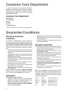
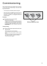
A. IGNITOR SWITCH
B. IGNITOR UNIT
1
2
L
N
0
220
240
1
2
3
4
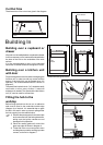
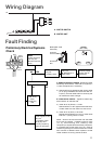
Wiring Diagram
Fault Finding
Preliminary Electrical Systems
Check
A. EARTH CONTINUITY CHECK - Appliance must be
electrically disconnected - meter set on Ω (Ohms) x
1 scale and adjust zero if necessary.
a) Test leads from any appliance earth point to earth
pin on plug. Resistance should be less than 0.1
Ω (Ohm), check all earth wires for continuity and
all contacts are clean and tight.
B. INSULATION CHECK - Appliance electrically
disconnected, all switches ON.
a) meter set on Ω (Ohms) x 1 scale.
Test leads from L to N in appliance terminal block.
If meter reads «0» then there is a short circuit.
b) meter set on Ω (Ohm) x 100 scale.
Repeat test with leads from L to E. If meter reads
less than ∞ (infinity) there is a fault.
NOTE - Should it be found that the fuse has failed
but no fault is indicated - a detailed continuity check
(i.e. by disconnecting and checking each
component) is required to trace the faulty component.
It is possible that a fault could occur as a result of
local burning/arcing but no fault could be found under
test. However a detailed visual inspection should
reveal evidence of burning around the fault.
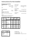
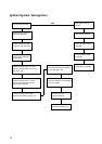
START
Isolate appliance
and carry out:
A: Earth Continuity
check.
Has inlet fuse blown?
Carry out:
C: Polarity check.
Electricity supply
should now be
satisfactory.
Carry out:
D: Resistance to
Earth check.
Inlet wiring
faulty.
Rectify any
fault.
Isolate appliance and
carry out:
B: Insulation check.
Rectify any fault
including replacing
fuses as necessary.
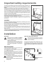
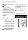
SOCKET
(face view)
PLUG (with cover
removed)
Earth Wire
Green/Yellow
Neutral Wire
Blue
Brown
Blue
Green
Yellow
Green
Yellow
Brown
Blue
( )
FUSE
( )
E
N
L
NO
YES
NO YES