12
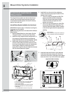
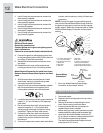
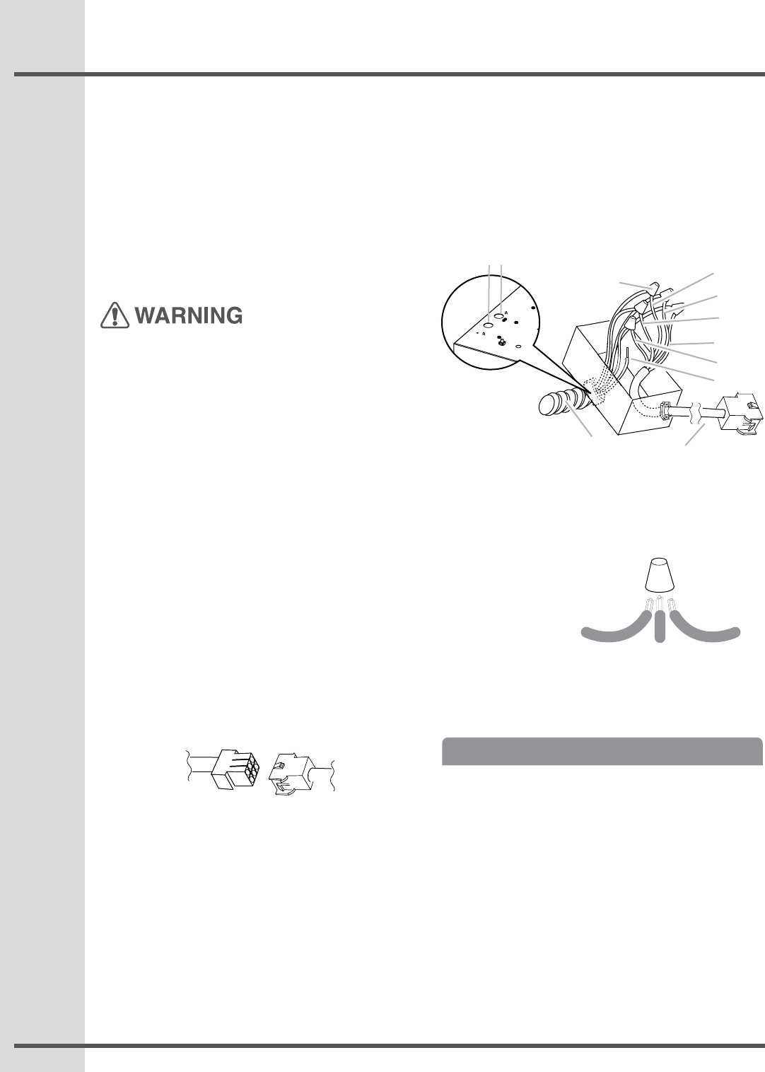
Use UL listed wire connectors and connect the
black wires (C) together.
Use UL listed wire connectors and connect the
white wires (D) together.
Use UL listed wire connectors and connect the
red wires (E) together.
Use UL listed wire connectors and connect the
blue wires (F) together.
Use UL listed wire connectors and connect the
gray wires (G) together.
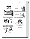
Electrical Shock Hazard
Electrically ground blower.
Connect ground wire to green and yellow ground
wire in terminal box.
Failure to do so can result in death or electrical shock.
Connect the green (or yellow/green) ground wire
to the green/yellow ground wire (H) in the terminal
box using UL listed wire connectors.
Reinstall the remote blower terminal box cover
and screw.
Reinstall the front cover of the remote blower
housing and secure it with 10 mounting screws.
Make Electrical Connection for Inside Hood Insert
Between Remote Blower Motor System and Hood
Insert
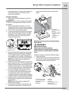
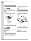
With the hood insert mounted (see the “Install
Hood Insert” section), locate the wiring cable
connector inside the hood insert.
Connect the 6-wire connector assembly supplied
with the remote blower motor system to the
mating cable connector from the hood insert.
Locate the terminal box inside the hood insert and
install a ½” (1.3 cm) UL listed or CSA approved
strain relief.
Run the wire ends from the 6-wire connector a
sembly through the ½” (1.3 cm) strain relief,
leaving enough wire length to make the wiring
conections. Tighten the strain relief screws.
Connect the wires from the 6-wire connector
asembly to the wires from the remote blower
system wiring conduit inside the hood insert
terminal box.
Connect the same color wires to each other (black
3.
4.
5.
6.
7.
8.
9.
10.
1.
2.
3.
4.
5.
6.
to black, white to white, etc.) using UL listed wire
connectors.
NOTE: Connect the green (or green/yellow) ground
wire from the Remote Blower Motor wiring conduit to
the green (or bare) ground wire from the home power
supply using UL listed wire connectors (refer to “Make
Electrical Power Supply Connection to Hood Insert”
section).
Go to the “Make Electrical Power Supply
Connection to Hood Insert” section.
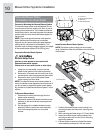
Prepare the Location
Disconnect power.
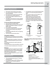
Determine which venting method to use: roof or
wall exhaust.
Select a at surface for assembling the hood
insert. Place covering over that surface.
It is recommended that the vent system be
installed before hood is installed.
Before making cutouts, make sure there is proper
clearance within the ceiling or wall for exhaust vent.
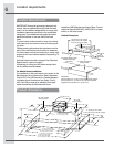
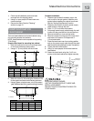
Hood insert should be installed a minimum 24”
(61 cm) above an electric cooktop surface and 30”
(76.2 cm) above a gas cook top surface.
The maximum recommended height over both
cook tops is 36” (91.44 cm).
7.
1.
2.
3.
•
•
•
B
C
D
E
F
G
H
I
A
J K
A. UL listed or CSA approved
1
⁄2” (1.3 cm) wiring conduit
B. UL listed wire connectors
C. Black wires
D.White wires
E. Red wires
F. Blue wires
G.Gray wires
H. Green (or green/yellow) wire
I. 6-wire connector assembly
J. Home power supply knockout
K. Remote Blower Motor knockout
Home
Power Supply
Remote
Blower Motor
Hood
Insert
Wire
Conector
Ground Wiring
Connections
Make Electrical Connections


