


20
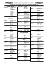
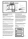
LEVELLING FEET
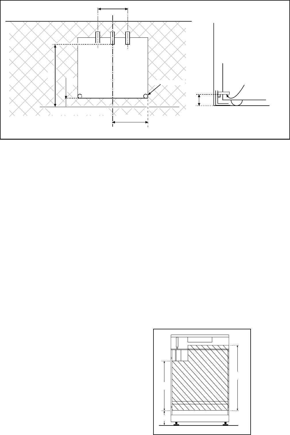
PENCIL LINE ON THE FLOOR
PLAN VIEW OF THE COOKER
480 mm.
100 mm.
300 mm.
245 mm.
WALL FACE
A
BACK OF COOKER
SIDE VIEW
OF THE COOKER
BASE OF COOKER
ENGAGEMENT EDGE FOR
STABILITY BRACKET
Fig. 3
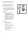
Fitting the Stability Bracket
(Not supplied)
If the cooker has to be installed with a flexible
supply pipe, it is necessary that a stability device
is fitted.
(See safety Requirements: Page 20).
If a stability bracket is to be fitted by the installer,
these instructions should be read in conjunction
with the leaflet packed with the stability bracket.
Place cooker in its intended position and level
cooker.
Mark off 250mm (11
1
/
2
") from the right hand
side of the cooker as shown, this is the centre
line of the bracket fixing.
Draw a line 100mm (4") from the front edge of
the levelling feet (see Fig. 2) and remove cooker
from its position. Mark off 480mm (19") back
from this line on the centre line of the bracket to
locate the front edge of the lower bracket.
Fix lower bracket (with two fixing holes) to the
floor, then measure height from floor level to
engagement edge on back of cooker, dimension
'A' of Fig. 2.
Assemble upper bracket to lower bracket so that
underside of bracket is dimension 'A' +3mm (1/
8") above floor level. Re-position cooker and
check that top bracket engages into cooker back
to a depth of 75mm (3"), as shown in Fig. 2.
Should the stability bracket currently installed not
allow the cooker to stand correctly, ask the
installer to replace it with the correct type.
Fig. 2
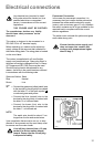
Connecting to Gas
This cooker is designed to be installed with an
appliance flexible connection. Connection is
made to the RC 1/2 (1/2" B.S.P.) threaded entry
pipe located just below the hotplate level on the
rear right-hand side of the cooker. Check for gas
soundness after connecting the gas supply.
The gas bayonet connector must be fitted in the
shaded area indicated in the diagram. Take into
account that it must be possible to pull the
cooker forward sufficiently. The hose must not
get caught on the stability bracket.
Note:
For certain types of gas bayonet connection
used, it may not be possible for the appliance to
be pushed fully back to the wall stops.
Important:
Flexible tubing MUST comply with BS.669
Current Edition.
FO 2434
FO 2435
600
450
130
Dimensions are given in millimeters
Dimensions are given in millimeters
250 mm.