


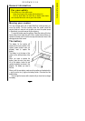
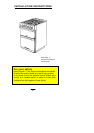


2. LEVELLING THE APPLIANCE
Adjustable levelling feet at the front and at the rear are provided on the base of the appliance.
Adjustment to suit floor conditions is obtained by rotating in or out the hexagonal feet from the underside of
the appliance.
A spirit level should be placed on one of the oven shelves to confirm that the appliance is correctly levelled.
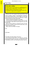
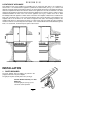
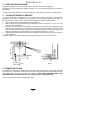
3. FITTING THE STABILITY BRACKET
It is recommended that if the appliance is to be installed with a flexible supply pipe a stability bracket
(SK.4729.A) is fitted and is available from your supplier (see Important Safety Requirements, Page 31).
These instructions should be read in conjunction with the leaflet packed with the stability bracket.
1. Place the appliance in its intended position and level appliance.
2. Mark off 250mm from the left hand side of the appliance as shown in dimension 'A', Fig 3a. This is the
centre line of the fixing bracket.
3. Draw a line 100mm from the front edge of the levelling feet (see Fig 3a) and remove appliance from its
position. Mark off dimension 'B' (see Fig 3a) back from this line on the centre line of the bracket to locate
the front edge of the lower bracket. Fix lower bracket (with two fixing holes) to the floor then measure the
height from floor level to engagement edge on back of appliance, dimension 'C' of Fig. 3b.
4. Assemble upper bracket to lower bracket so that underside of bracket is dimension 'C' +3mm above floor
level. (see Fig. 3b).
Reposition appliance and check that top bracket engages into appliance back as shown in Fig. 3b.
Fig.3a Fig.3b
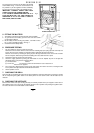
4. CONNECTING TO GAS
This appliance is designed to be installed with an appliance flexible connection only. Supply piping should not
be less than R³/
8. Connection is made to the Rc½ (½" B.S.P.) female threaded entry pipe located just below
the hotplate level on the rear left hand side of the appliance. NOTE: ONLY LIQUID SEALANTS TO BE
USED WHEN INLET GAS PIPE IS FITTED I.E.: DO NOT USE P.T.F.E. SEALANT TAPE.
Check for gas soundness after connecting the gas supply.
R E N O W N S I 50
33
487mm (B)
(A)
250mm
(C)
100mm
20mm