


97644C (Rev. B - 2/04)
ELKAY MANUFACTURING COMPANY 2222 CAMDEN COURT OAK BROOK, IL 60523 630.574.8484
REPAIR SERVICE INFORMATION TOLL FREE NUMBER 1.800.260.6640
FOR PARTS, CONTACT YOUR LOCAL DISTRIBUTOR OR CALL 1.800.323.0620
ERW20-1C
ITEM
NO.
PART NO.
1
2
3
4
5
6
7
8
9
10
11
12
13
14
15
16
17*
18
19
20
21
22
23
24
25
26
27
28
29
30
31
50196C
28180C
23101C
23104C
28178C
28179C
23089C
28175C
27957C
28176C
30235C
30768C
30812C
35882C
35895C
35921C
36074C
30233C
30234C
66632C
66625C
70772C
66204C
66629C
36079C
35845C
35846C
30560C
70482C
70483C
70274C
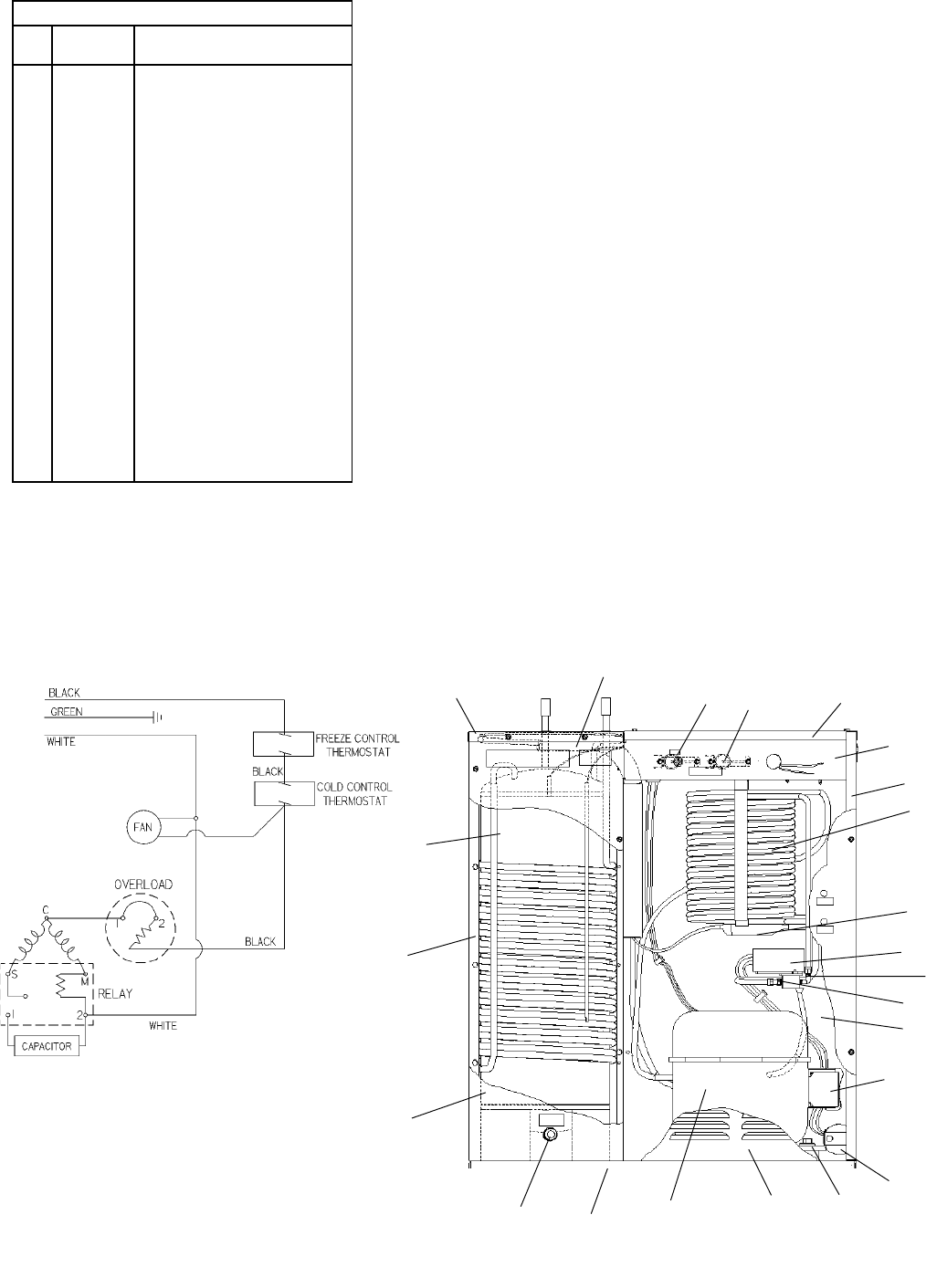
ITEMIZED PARTS LIST
DESCRIPTION
*INCLUDES RELAY & OVERLOAD. IF UNDER
WARRANTY, REPLACE WITH SAME COMPRESSOR
USED IN ORIGINAL ASSEMBLY.
NOTE: All correspondence pertaining to any of the
above water cooler or orders for repair parts MUST
include model number and serial number of cooler, name
and part number of replacement part.
Grommet
Panel Insulation Box (Rear)
Panel End
Box Insulation (Front)
Terminal Box
Grille
Cover Terminal Box
Rear Panel
Cover Insulation Box
Base Ass'y
Terminal Cover
Solenoid Valve
Overload
Cold Control
Cold Control Freeze Protect
Capacitor
Compressor Service Pak
Overload Spring
Clip Compressor
Condenser
Evaporator
Drain Plug
Drier
Heat Exchanger
Relay
Cap-Capacitor End
Bracket-Capacitor
Terminal Cover
Male Connector Fitting
Elbow Fitting
Compressor Mounting Sleeve
WIRING DIAGRAM
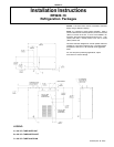
INSTALLATION
1. Potable water inlet and outlet are 3/8" (9 mm) O.D. tube located on
top of unit. Water cooled condenser inlet and outlet are 3/8" (9 mm)
O.D. tube located on right front of unit. Installer to provide air gap at
condenser water outlet to comply with local plumbing specifications.
Contractor to supply connections as required.
2. Connecting lines to be of copper, thoroughly flushed to remove all
foreign matter before being connected to cooler. If flushing does
not remove all particles, a water strainer should be installed in supply
line.
3. Connect cooler to building supply line with a shut-off valve and install
a union connection between the valve and cooler.
4. Electrical: Make sure power supply is identical in voltage, cycle, and
phase to that specified on cooler serial plate. Never wire compressor
directly to the power supply
START-UP
1. Open supply line valve.
2. Purge air from all water lines by operating bubbler valve of fountain.
3. Connect to electrical power.
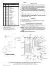
TROUBLE SHOOTING & MAINTENANCE
Temperature Control: Factory set for 50° F water under normal
conditions. To adjust water temperature, turn screw on Item No. 14
clockwise for colder, counter clockwise for warmer.
Ventilation: Cabinet louvers should be periodically cleaned with brush,
air hose or vacuum cleaner. Excess dirt or poor ventilation can cause
no cold water and compressor cycling on the compressor overload
protector
Lubrication: Motors are lifetime lubricated.
9
14
15
7
5
3
20
23
12
8
11,13,18,
19, 25, 28
16, 26, 27
1, 31
6
17
10
22
4
2
21
24
30
29