


97582C (01/21/2000)
HRC32W
DESCRIPTION
23152C
28070C
27698C
28032C
23158C
23159C
26701C
34783005
35882C
66218C
31723000
30440C
30768C
43242004
48000036
30248C
48000070
48000067
48000069
48000068
19037000
100806740570
66216C
70772C
31738002
70020C
1
2
3
4
5
6
7
8
9
10
11
12
13
14
*15
16
17
18
19
20
21
22
23
24
25
26
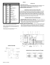
PART NO.
BOX - INSULATION
BASE ASSY
PANEL
PANEL - FRONT/REAR
COVER - INSULATION BOX
BRACKET - CONDUIT
CABINET
WASHER - LOCK
CONTROL - COLD
CONDENSER ASSY
STRAINER
CAPACITOR
SOLENOID VALVE
CAPILLARY TUBE
COMPRESSOR
OVERLOAD
GASKET - TERM COVER
OVERLOAD SPRING
BALE STRAP
COVER - TERMINAL
CLIP - COMPRESSOR MTG
GROMMET - COMPRESSOR MTG
EVAPORATOR ASSY
EVAPORATOR DRAIN PLUG
DRIER
NUT
ITEM NO.
PARTS LIST
*INCLUDES RELAY & OVERLOAD. IF UNDER WARRANTY REPLACE
WITH SAME COMPRESSOR USED IN ORIGINAL ASSEMBLY.
NOTE: ALL CORRESPONDENCE PERTAINING TO ANY OF THE ABOVE
WATER COOLERS OR ORDERS FOR REPAIR PARTS MUST INCLUDE
MODEL NO. AND SERIAL NO. OF COOLER, NAME AND PART NO. OF
REPLACEMENT PART.
NOTE: FOR USE WITH PHOTO PROCESSING APPLICATIONS,
ADJUST THERMOSTAT TO WARMER SETTINGS.
The grounding of electrical equipment such as telephone, computers, etc., to water
lines is a common procedure. This grounding may be in the building, or may occur
away from the building. This grounding can cause electrical feedback into a water
chiller, creating an electrolysis which causes a metallic taste or an increase in the
metal content of the water. This condition is avoidable by using the proper materials
indicated below. Drain fittings which are provided by the installer should be plastic to
electrically isolate the chiller from the building plumbing system.
Temperature Control: Factory set for 50°F water (± 5°) under normal conditions. For
colder water, adjust screw on item no. 9 clockwise.
Ventilation: Cabinet louvers and condenser fins should be periodically cleaned with a
brush, air hose, or vacuum cleaner. Excess dirt or poor ventilation can cause no
cold water and compressor cycling on the overload protector.
Lubrication: Motors are lifetime lubricated.
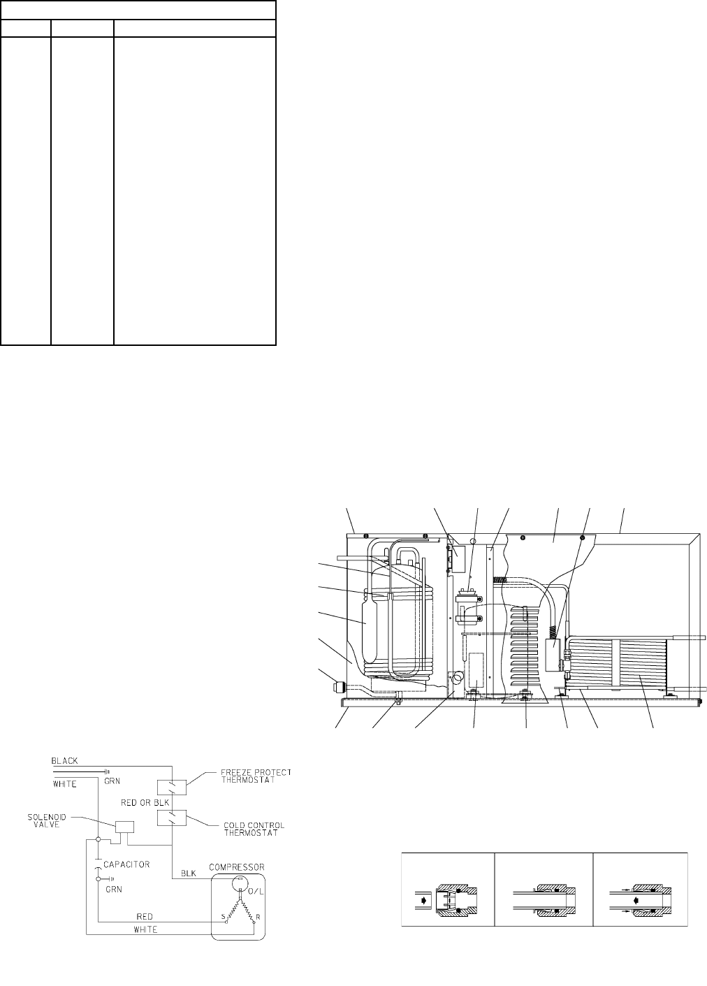
Actuation of Quick Connect Water Fittings: Cooler is provided with lead-free plug
which utilizes an o-ring seal. To remove plug from cooler, relieve water pressure,
pull the collar towards the fitting and pull the fitting off the tube. To install plug,
push fitting straight onto tubing until it reaches a positive stop, approximately 3/4.
IMPORTANT! INSTALLER PLEASE NOTE:
TROUBLE SHOOTING & MAINTENANCE
START-UP
1. Open supply line valve.
2. Purge all air from all water lines by operating bubbler valve of fountain to which
cooler is connected. A steady stream flow assures that all air is removed.
3. Rotate fan blade to assure proper clearance and free action.
4. Connect to proper electrical power.
TUBE IS SECURED
IN POSITION
SIMPLY PUSH IN
TUBE TO ATTACH
PUSH IN COLLET
TO RELEASE TUBE
PUSHING TUBE IN BEFORE
PULLING IT OUT HELPS TO
RELEASE TUBE
OPERATION OF QUICK CONNECT FITTINGS
WIRING DIAGRAM
5
9
12
3413
7
14
23
25
1
24
2
8, 26
6
15,16,17
18,19,20
21, 22 14
11
10