


3
INSTALLATION (cont.)INSTALLATION (cont.)
INSTALLATION (cont.)INSTALLATION (cont.)
INSTALLATION (cont.)
12. The gas valve should now be free to slide out of burner
and off of mounting bracket. Take care not to disturb the
air shutter.
13. Remove inlet fitting from old gas valve and set it aside.
Take care not to damage the sealing surfaces. This part
will be reused.
14. Clean the threads of the inlet fitting. Apply pipe sealant
(approved for all gases) to the threads. Install the fitting
into the inlet of the new valve and tighten to 200 lbf-in
(16.6 lbf-ft) using a 3/8 inch hex head wrench.
15. Remove orifice screw from old gas valve and set it
aside. Take care not to damage the sealing surfaces.
This part will be reused.
16. Inspect the threads of the orifice screw and clean if
necessary.
17. Inspect the orifice hole and remove any foreign material.
18. Install orifice screw into new valve and tighten to 40 lbf-
in. Do not use any pipe sealant.
19. Slide the outlet boss of the new valve into the burner.
Take care not to disturb the air shutter.
20. Fasten the gas valve to the mounting bracket using the
screw(s) removed earlier.
21. Connect the gas inlet pipe to the inlet fitting by threading
the union together and tightening to 150 lbf-in (12.5 lbf-
ft).
22. Insert the burner assembly back into the dryer so that
the gas inlet pipe exits through the square hole in the
back of the dryer cabinet, and the burner fits inside the
heat exchanger. Take care not to bump or jar igniter. It is
very fragile.
23. Fasten the mounting bracket to the bottom of the dryer
cabinet using the screw removed earlier.
24. Reconnect the wiring harness to the igniter and the gas
valve.
25. Reconnect the exhaust vent duct to the back of the
dryer.
26. Apply pipe sealant to the threads of the inlet gas pipe
and reconnect the gas line to the back of the dryer and
tighten.
27. Turn on gas supply and
ChecChec
ChecChec
Chec
k fk f
k fk f
k f
or leaksor leaks
or leaksor leaks
or leaks.
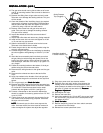
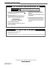
28. Remove the outlet pressure tap from the gas valve (see
figure 3). Apply pipe sealant to the 1/8-inch NPT threads
of a hose barb. Install the hose barb into the outlet
pressure tap and tighten to 40 lbf-in (see figure 4).
29. Connect a manometer to the hose barb. Manometer
should be capable of measuring pressure from 2.5" WC
up to 14.0" WC.
30. If entire front cover was removed, the connector for the
door switch must be temporarily jumpered. Otherwise
the dryer will not function.
NONO
NONO
NO
TETE
TETE
TE: On some dryers, the front cover supports the
drum. On these models, the drum must be removed in
order to energize the system and adjust the regulator.
Outlet Pressure
Tap (Plugged)
Hose Barb Installed
in Outlet Pressure Tap
Figure 3Figure 3
Figure 3Figure 3
Figure 3
Figure 4Figure 4
Figure 4Figure 4
Figure 4
31. Plug dryer power cord into electrical socket.
3232
3232
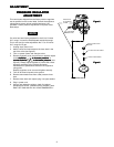
32. Energize dryer and verify ignition. Also observe the
reading on the manometer. It should read the same
outlet pressure as stated on the rating plate on the old
gas valve. If it does not, see section on
PressurePressure
PressurePressure
Pressure
Regulator AdjustmentRegulator Adjustment
Regulator AdjustmentRegulator Adjustment
Regulator Adjustment.
33. De-energize the dryer.
34. Remove the hose barb.
35. Apply pipe sealant to the 1/8 inch NPT plug screw. Install
the 1/8 inch NPT plug screw into the outlet pressure tap
and tighten 40 lbf-in.
36.
Check for leaksCheck for leaks
Check for leaksCheck for leaks
Check for leaks.
37. Remove temporary jumper from door switch connector
and reconnect to door switch.
38. Reinstall the access panel/front cover.