4A.3 Temperature Setpoint for Chiller
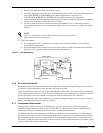
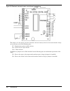
The temperature setpoint for the chiller should be set by turning the potentiometer. To obtain an
accurate setpoint, connect a voltmeter (millivolt) to TP1 and TP2. The readout will display tem-
perature in degrees Fahrenheit. Turn the potentiometer to the desired setpoint.
A “well” sensor is factory-piped and wired to accurately measure the temperature of the water
leaving the chiller. This sensor provides input to the Electronic Hot Gas Bypass Controller. The
sensor changes electrical resistance in response to temperature changes. To check or troubleshoot
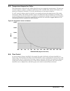
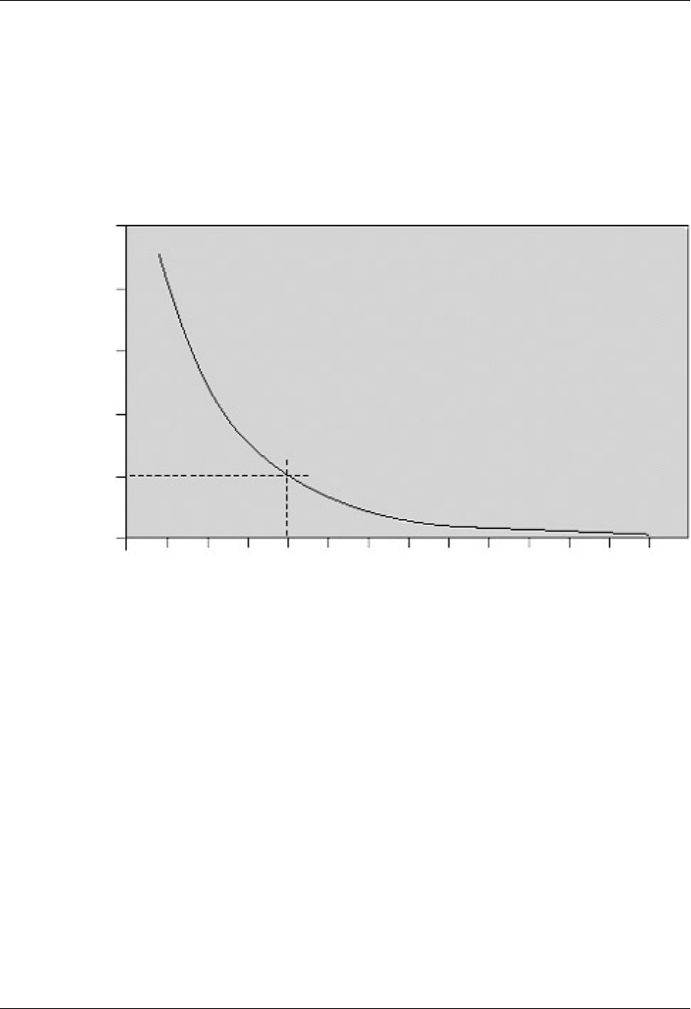
the sensor, disconnect it from the controller and measure the resistance. Figure 3E shows the
relationship between temperature and resistance.
Figure 3E Temperature sensor resistance
4A.4 Flow Control
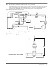
A circuit setter is factory-installed in the supply line and a ball valve is factory-installed in a
bypass loop. The desired system flow to the load should be set by adjusting the circuit setter to the
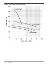
required flow rate. If a flow rate of less than 5 gpm is required, the ball valve should be adjusted
to keep the overall system flow rate up. If low suction pressures are present, the circuit setter
should be set to a higher flow, with the bypass valve used to control flow to the load.
TEMPERATURE (Degrees Fahrenheit)
OHMS
20,000
30,000
50,000
-60
10,000
40,000
-40 -20 0 604020 80 100 120 140 160 180 200
Maintenance 18E


