F. CABINET ITEMS
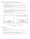
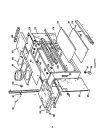
1. Magnetic catches 111 are a push-fit in front top panel 109.
2. To remove front top panel 109, remove both sliding t abletops completely (see A.1.) and magnetic catches
111. Drill out the rivet at each end of the front slide panel using a 3mm bit. Use extreme care when drilling
Withdraw leg top caps 108, and then remove the front top panel assembly. Refit in reverse order.
3. Castor wheels 116 are a push-fit onto castor wheel inserts 117. The castor wheel inserts are a push-fit into
the cabinet. Remove by prising out with care.
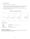
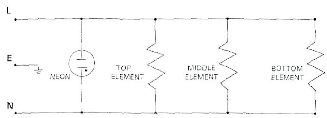
THEORETICAL WIRING DIAGRAM
SPECIFICATION
Voltage 120 V ac. 60Hz
Loading 410 W (Top 110 W, Middle 110 W, Bottom 190 W)
Cord length 2 m
Pre-heat time 30 minutes approx
Finish See text
Dimensions (approx) 725mm W x 380mm D x 695mm H
SERVICE INFORMATION
The elements used in t his appliance are of the adhesive variety and cannot be removed easily. For this reason,
elements and plates are supplied as complete assemblies.
4


