


PHÖNIX Messtechnik GmbH, Salzschlirferstr. 13, D-60386 Frankfurt/M., Germany, Tel: +49/69/416742 -20, Fax: -29
12
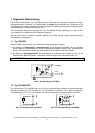
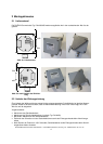
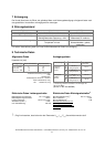
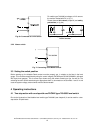
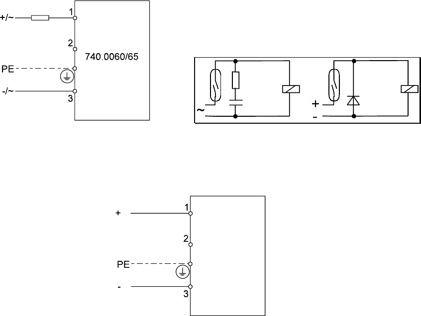
Fig. 6a: Connected as a mini switch
For switch type 740.0060 at voltages >24 V remove
the resistor marked with R1 (s. fig. 1).
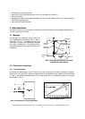
Please observe
limit values
(chapter 8) and
safety
precautions
(s. fig. 6b).
Fig. 6b: safety precautions for operation in low
DC/AC circuits.
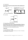
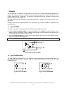
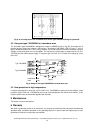
3.2.3 Namur switch
Fig. 7: Connecting of the Namur switch
3.3 Setting the switch position
Before starting-up, the bistable Reed contact must be properly set, in relation to the float in the level
gauge. This can be accomplished by using the control magnet (PHÖNIX part BG10XXXXMAKU, delivered
with liquid level gauges). This is moved up or down along the switch according to figs. 3a and 3b. The
switching function can be tested using an appropriate alarm or ohmmeter on the terminals 1 and 3. In this
case the system voltage, external wires must be disconnected !
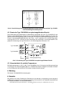
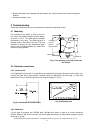
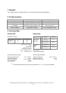
4 Operating instructions
4.1 Two-step action with overlap with one PHÖNIX type 740.0060 level switch
Due to the Hysteresis of the bistable level switch type 740.0060 (see chapter 9) it can be used for a two-
step action of liquid levels.
low load
740.0065NA