


PHÖNIX Messtechnik GmbH, Salzschlirferstr. 13, D-60386 Frankfurt/M., Germany, Tel: +49/69/416742 -20, Fax: -29
11
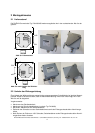
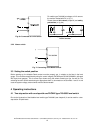
• Mount the bracket on the opposite side of the switch box. Use the second row of holes to keep the
distance.
• Remount the switch cover
3 Commissioning
Authorised skilled personnel only recommended to connect the electrical circuits.
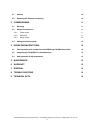
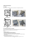
3.1 Mounting
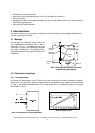
The mounting of the switch is done by two col-
lars, which are supplied together with the switch,
as shown in Fig. 4. The cable gland is directed
downwards in any case. The switching point is
situated nearby the middle of the box. The heat
protection is optional for high temperature appli-
cations and is situated between the switch box
and the mounting bracket.
Fig. 4: The mounting to the tube is done by
two collars.
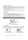
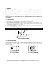
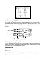
3.2 Electrical connections
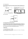
3.2.1 Power switch
In AC applications the function is comparable to a mechanically operating switch and can be used in con-
junction with load relays, gate switches, solenoid valves etc. Because of the wiring (fig. 1) of the solid
state switch (Triac) a small permanent current will pass through C1 (47nF).
Fig. 5a: Connected as a power switch
Fig. 5b: Minimum load
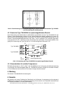
3.2.2 Miniswitch
For this type of operation, the PHÖNIX type 740.0060 level switch is used as a normal mechanical
(REED) switch for low AC/DC-currents. The usual safety precautions for Reed switch contacts must be
observed (s. fig. 6b).
Last
housing
mounting screws
holder
optional
heat protection
mounting
bracket
collars
switching
point
M20x1
,
5